


8
ATICS-DIO_D00080_03_Q_DEEN / 11.2020
ATICS-...-DIO
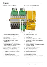
Durch leichtes Ziehen am unteren Teil des
Gehäuses prüfen, ob Verriegelungsschieber
richtig eingerastet ist.
3. Alle Klemmen mit Innensechskantschrauben
festschrauben. Anzugsmoment: 5 Nm.
4. Klemmenabdeckungen befestigen.
5. Schrauben (D) festdrehen (PZ1, 8,8 lb-in,
1 Nm).
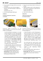
ATICS® auf Montageplatte montieren
i
• Maßbild Rückansicht beachten.
• Befestigungsschrauben M5 nutzen.
I
V
orsicht
:
Schraubenköpfe oder
Unterlegscheiben verringern Spannungs-
abstände.
Befestigungsschrauben dürfen
nicht zu dicke Schraubenköpfe oder
Unterlegscheiben haben, damit
Spannungsabstände zu aktiven Leitern groß
genug sind. Bei Montage auf leitendem
Material: Platte erden und unter den Bereich
der Anschlüsse Isolierstoff unterlegen.
1. Innensechskantschrauben der Klemmen (C)
lösen.
2. Grüne Steckvorrichtungen (D) oben und unten
entfernen.
3. Schwarze Brücke unten (E) entfernen.
4. ATICS® mit Befestigungsschrauben M5 (22 lb-
in, 2,5 Nm) auf Montageplatte befestigen (sie-
he Maßbild).
5. Schwarze Brücke unten (E) einstecken.
!
C
D
E
N
Check that the slide lock is properly snapped
into position by pulling slightly the lower part
of the enclosure.
3. Secure all terminals with Allen screws.
Tightening torque: 5 Nm.
4. Fasten the terminal covers.
5. Tighten the mounting screws (D) (PZ1,
8.8 lb-in, 1 Nm).
Mounting the ATICS® on mounting plate
i
• Observe dimension drawing rear view.
• Use fixing screws M5.
I
c
aution
:
Screw heads or washers reduce
voltage clearance.
Provide for sufficient lea-
rance to live conductors (voltage clearance)
by using mounting screws with flat screw
heads and flat washers. If mounted on elec-
trically conductive material: the mounting
plate has to be earthed and the area under
the terminals has to be covered with insula-
ting material.
1. Undo the Allen screws of the terminals (C).
2. Remove the green connectors (D) top and bot-
tom
3. Remove the black bridge (E) bottom
4. Fasten the ATICS® to the mounting plate with
M5 (22 lb-in, 2.5 Nm) mounting screws (see di-
mension diagram).
5. Insert the black bridge (E), bottom


