background image

Installation, connection and commissioning

28

isoEV425_D00126_09_M_XXEN/03.2019

4.3

Commissioning

1.

Check that 

the ISOMETER® is properly connected to the system to be 

monitored.

2.

Connecting supply voltage 

U

s

 to the ISOMETER®

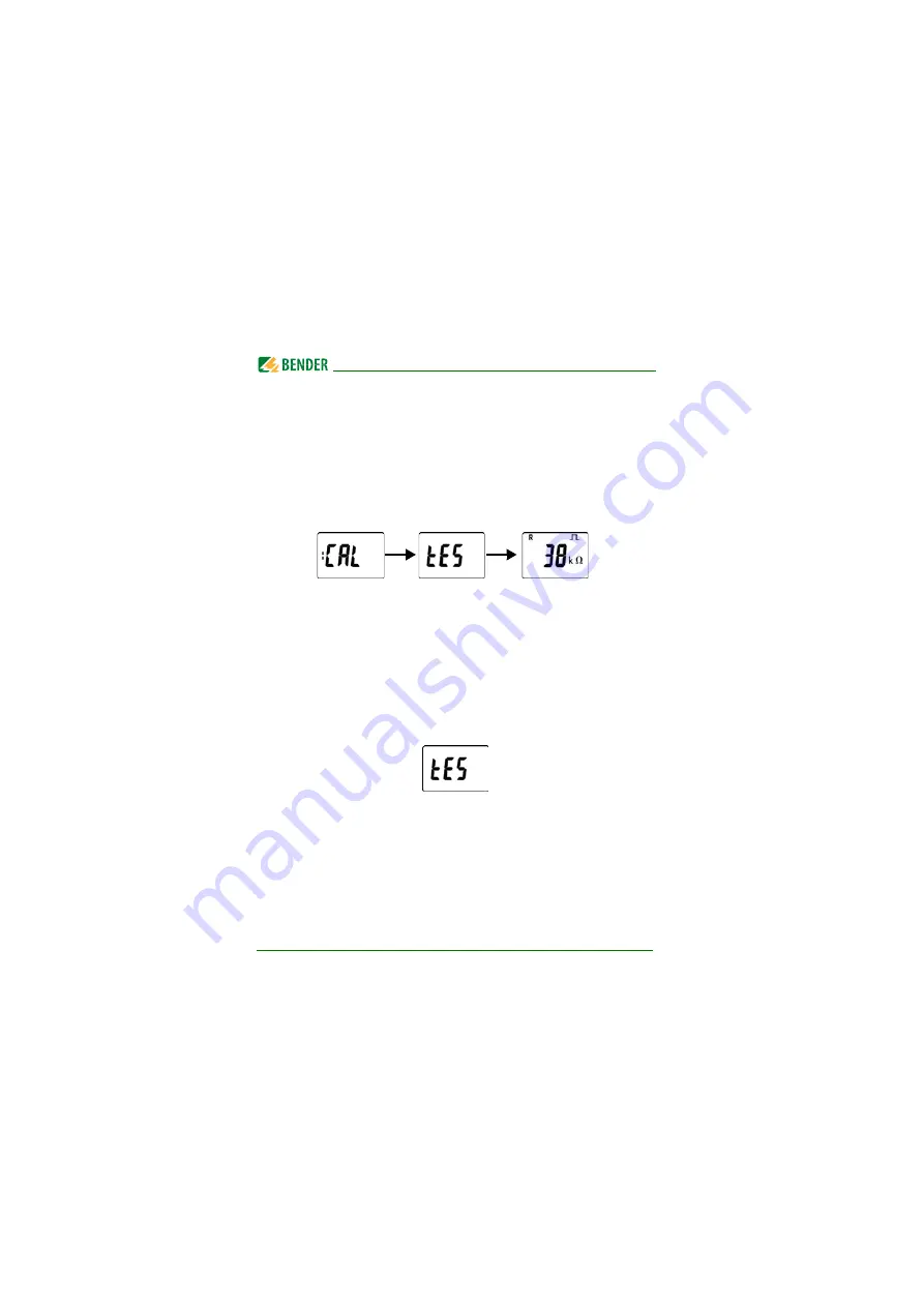
The device carries out a calibration, a self test and adjusts itself to the IT 
system to be monitored. When high system leakage capacitances are 
involved, this procedure may take up to 4 min. The standard display 
then appears showing the present insulation resistance, e.g.: 

The pulse symbol signals an error-free update of the resistance and 
capacitance measured values. If the measured value cannot be 
updated due to disturbances, the pulse symbol will be hidden.

3.

Start a manual self test 

by pressing the test button "T". Whilst the test 

button is pressed and held down, all display elements available for this 
device are shown. During the test, the "tES" symbol flashes. Any inter-
nal malfunctions detected are shown on the display as error codes
(see 

Page 17

). The alarm relays are not checked during the test (factory 

setting). The setting can be changed in the "out" menu, so that the 
relays switch to the alarm state during the manual self test. 

4.

Checking factory settings for suitability

Are the settings suitable for the installation to be monitored?
The list of factory settings are shown in the table in 

Chapter 5.

5.

Checking the function using a genuine insulation fault

The ISOMETER® in the system being monitored can be checked using, 
for example, a suitable resistance to earth.

Summary of Contents for AGH420

Page 1: ...2019 ISOMETER isoEV425 isoEV425HC with AGH420 coupling device Insulation monitoring device for unearthed DC circuits IT systems for the charging of electric vehicles Software version D0430 V2 xx D0640...

Page 2: ...5 Gruenberg Germany P O Box 1161 35301 Gruenberg Germany Tel 49 6401 807 0 Fax 49 6401 807 259 E mail info bender de Web www bender de Bender GmbH Co KG All rights reserved Reprinting only with permis...

Page 3: ...2 Safety instructions 12 2 1 General safety instructions 12 2 2 Work activities on electrical installations 12 2 3 Intended use 13 3 Function 14 3 1 Device characteristics 14 3 2 Functional descriptio...

Page 4: ...29 5 1 Display elements 30 5 2 Menu structure 31 5 3 Menu AL 32 5 3 1 Response value setting 32 5 4 Menu out 33 5 4 1 Configuration of the relay operating mode 33 5 4 2 Relay alarm assignment r1 and r...

Page 5: ...the Master 42 7 3 Exception code 42 7 3 1 Structure of the exception code 42 8 Modbus register assignment of the ISOMETER 43 8 1 ISOMETER device specific data type 49 8 1 1 Device name 49 8 1 2 Measur...

Page 6: ...f these symbols is explained below This manual is intended for electrically skilled per sons working in electrical engineering and electro nics DANGER This signal word indicates that there is a high r...

Page 7: ...n Germany only 0700BenderHelp Tel and Fax E Mail support bender service com 1 2 2 Repair service Repair calibration update and replacement service for Bender prod ucts Repairing calibrating testing an...

Page 8: ...eter setting maintenance troubleshooting for Bender products Analysis of the electrical installation in the building power quality test EMC test thermography Training courses for customers Telephone 4...

Page 9: ...tandard software as part of deliveries modificationsandchanges to general delivery conditions for products and services in the electrical indus try set out by the ZVEI Zentralverband Elektrotechnik un...

Page 10: ...sioning operation and maintenance of the device Unauthorised changes to the device made by parties other than the manufacturer Non observance of technical data Repairs carried out incorrectly and the...

Page 11: ...mmu nity In Germany these policies are implemented through the Electrical and Electronic Equipment Act ElektroG According to this the following applies Electrical and electronic equipment are not part...

Page 12: ...d regulations must be complied with The European stand ard EN 50110 can be used as a guide Only skilled persons are permitted to carry out the work ne cessary to install commission and run a device or...

Page 13: ...stems with nominal system voltages of DC 0 1 000 V DC components existing in 3 N AC AC DC systems do not in fluence the operating characteristics when a minimum load current of DC 10 mA flows A separa...

Page 14: ...with connection monitoring Selectable start up delay response delay and delay on release Two separately adjustable response value ranges of 1k 500 k Alarm 1 Alarm 2 Alarm signalling via LEDs AL1 AL2...

Page 15: ...linsulationresistanceRF and the faulty conductor R using the following formula Also from a minimum value of the nominal system voltage the ISOMETER de termines the insulation resistance RUGF from the...

Page 16: ...nd R2 can be found in the response value menu AL see table inChapter 5 3 The value R1 can only be set higher than the value R2 If the insulation resistance RF reaches or falls below the activated valu...

Page 17: ...evice error with the parameter Err in the out menu in the alarm assignment Error codes If contrary to expectations a device error should occur error codes will ap pear on the display Some of these are...

Page 18: ...meter in the menu SEt to S Ct off This allows the ISOMETER to enter measurement mode quickly after connecting the supply voltage Us Automatic self test The device runs a self test after connecting the...

Page 19: ...t of the system connection may take considerable time due to system disturbances or may even provide incorrect results the system connection monitoring can be disconnected us ing the parameter nEt in...

Page 20: ...nded that the value set for the S AL pa rameter value is identical for both relays 3 2 6 Measuring and response times The measuring time is the period essential for the detection of the measured value...

Page 21: ...or the period of ton without interruption Every time the threshold value is exceeded within the time ton the response delay ton restarts once again Every alarm message listed in the alarm assignment h...

Page 22: ...s case it can only be reset via the interface Only one ISOMETER may be control led via a test reset button A galvanic parallel connection of several test or re set inputs for testing multiple insulati...

Page 23: ...y sends an ASCII data string with a cycle of approximately 1 second Communication with the ISOMETER within this mode is not possible and no additional transmitter may be connect ed to the RS 485 bus c...

Page 24: ...sition the rear mounting clips so that they project beyond the enclosure a second mounting clip is required see ordering information Fix the device with two M4 screws see the following sketch DANGER R...

Page 25: ...dimension diagram and sketches outlining how the device can be screw mounted and DIN rail mounting are shown below All dimensions in mm The front plate cover can be opened at the lower part marked wit...

Page 26: ...urfaces If the AGH420 is operated at mains voltages 800 V the temperature of the enclosure may exceed 60 C Once the device is connected to the mains voltage avoid touching the surfaces of the device U...

Page 27: ...for A1 A2 is to be used L1 L2 Connection to the 3 N AC AC or DC system to be monitored Up AK1 GND AK2 Connect the terminals of the AGH420 to the corresponding terminals of the ISOMETER T R Connection...

Page 28: ...ces the pulse symbol will be hidden 3 Start a manual self test by pressing the test button T Whilst the test button is pressed and held down all display elements available for this device are shown Du...

Page 29: ...gation and settings Up and down button navigate up or down in the menu settings increase or decrease values MENU Pressing the MENU Enter button for more than 1 5 s Starts menu mode or when the device...

Page 30: ...e capacitance Ce 2 Monitored conductor 3 Voltage type DC Voltage type AC 4 Measured values and units 5 Password protection is activated 6 In the menu mode the operating mode of the respective alarm re...

Page 31: ...r the history memory ESC Go to the next higher menu level Enter or t 5 min k R R k C F U L1 L2 V UL1 V UL2 V R U R k Standard display Measurement display Menu Esc Menu selection AL out t SEt InF HiS E...

Page 32: ...resis value see table below the alarm will be cleared Also in the response value menu AL the parameters U and U for monitoring the nominal system voltage Un can be activated or de activated The maximu...

Page 33: ...unsymmetrical insulation fault only the alarm correspond ing to the assigned conductor L1 or L2 will be displayed Otherwise the messages for L1 and L2 are shown together Relay K1 Relay K2 Description...

Page 34: ...figuration FAC Factory setting Cs User settings r1 U V off r2 U V on Alarm Un Overvoltage r1 test off r2 test off Manually started device test r1 S AL off r2 S AL off Device start with alarm Display F...

Page 35: ...Value range FAC Cs Adr 0 3 90 3 Bus adr Adr 0 deactivates BMS as well as Modbus and acti vates isoData with continu ous data output 115k2 8E1 Adr 1 1 2k 115k Baud rate BMS bus 9k6 7E1 1 2k 115k Modbus...

Page 36: ...on Value range FAC Cs t 0 10 0 s Start up delay when starting the device ton 0 99 0 s Response delay K1 and K2 toff 0 99 0 s Delay on release K1 and K2 test OFF 1 24 24 h Repetition time device test D...

Page 37: ...esistance after a maximum of 5 min The pulse symbol indicates a current measured value If this symbol does not appear the measurement is still run ning and the latest valid measured value will be disp...

Page 38: ...C 1 20 kVDC Resolution 1 VDC 10 VDC U L2 V Residual voltage L2 PE UL2e 0 VDC 1 20 kVDC Resolution 1 VDC 10 VDC R Fault location in 100 100 Indication only from Un 100 VDC RL1F 200 RF 100 x RL2F 200 RF...

Page 39: ...ice interface BMS bus protocol ASCII characters are used for the data transfer BMS channel no Operation value Alarm 1 RF Pre alarm R1 2 RF Alarm R2 3 Ce 4 Un Undervoltage 5 Un Overvoltage 6 Connection...

Page 40: ...egisters of the ISOMETER using the function code 0x03 For this purpose the start address and the number of the registers to be read out have to be en tered Up to 125 Words 0x7D can be read out by one...

Page 41: ...ster sends a command to the ISOMETER In this example the master addresses the ISOMETER with address 3 and re quests that the content of the register with address 3003 is set to 2 Byte Name Example Byt...

Page 42: ...TER Modbus address 0x03 Byte 1 Function code 0x10 Byte 2 3 Start register 0x0BBB Byte 4 5 Number of registers 0x0001 Byte 6 7 CRC16 Checksum 0x722A Exception code Description 0x01 Impermissible functi...

Page 43: ...with alarm 2 or only the device fault Register Measured value Device fault Without alarm Alarm 1 Alarm 2 1000 to 1003 RF Insulation fault 71 no alarm RF Insulation fault 1 pre warning RF Insulation f...

Page 44: ...to Chapter 8 1 2 2 1016 to 1019 UL1e Voltage 76 no alarm 1020 to 1023 UL2e Voltage 76 no alarm 1024 to 1027 Fault location in 1022 no alarm 1028 to 1031 RUGF Insulation fault 71 no alarm 1032 to 1035...

Page 45: ...002 RW Reserved 3003 RW Reserved 3004 RW Reserved 3005 RW Pre alarm value resistance meas urement R1 UINT 16 k R2 500 3006 RW Reserved 3007 RW Alarm value resistance meas urement R2 UINT 16 k 1 R1 300...

Page 46: ...RW Operating mode of relay 2 r2 UINT 16 0 n o 1 n c 3015 RW Bus address Adr UINT 16 0 3 90 3016 RW Baud rate Adr 1 UINT 16 0 BMS 1 1 2 k 2 2 4 k 3 4 8 k 4 9 6 k 5 19 2 k 6 38 4 k 7 57 6 k 8 115 2 k 3...

Page 47: ...d 3024 RW Test of the sys tem connection during devicetest nEt UINT 16 0 Inactive 1 Active 3025 RW Device test dur ing device start S Ct UINT 16 0 Inactive 1 Active 3026 RW Request stop mode 0 deacti...

Page 48: ...vice test UINT 16 0x5445 TE 8006 WO Clear fault mem ory UINT 16 0x434C CL 9800 to 9809 RO Device name UNIT 16 ASCII refer to Chapter 8 1 1 9820 RO Software ID number UINT 16 9821 RO Software version n...

Page 49: ...s 4 regis ters The first measured value register address is 1000 The structure of a channel is always identical Content and number depend on the device The structure of a channel is shown with the exa...

Page 50: ...ting point value of the channels Presentation of the bit order for processing analogue measured values ac cording to IEEE 754 S Sign E Exponent M Mantissa Word 0x00 0x01 Byte HiByte LoByte HiByte LoBy...

Page 51: ...alues are reserved The complete byte is calculat ed from the sum of the alarm type and the test type Bit 7 6 5 4 3 2 1 0 Description Test external Test internal Reserved Reserved Reserved Alarm Error...

Page 52: ...t and the range of validity Bit 7 6 5 4 3 2 1 0 Description Unit 0 0 0 0 0 Invalid init 0 0 0 0 1 No unit 0 0 0 1 0 0 0 0 1 1 A 0 0 1 0 0 V 0 0 1 0 1 0 0 1 1 0 Hz 0 0 1 1 1 Baud 0 1 0 0 0 F 0 1 0 0 1...

Page 53: ...unction Bit Display indication Description 0 Reserved When reading always 0 When writing any value 1 x Err Device error E xx 2 rx R1 Pre alarm R1 Fault RF at L1 3 rx R1 Pre alarm R1 Fault RF at L2 4 r...

Page 54: ...e Value Measured value description alarm message operating message Note 0 1 0x01 Insulation fault 71 0x47 Insulation fault Insulation resistance RF in 76 0x4C Voltage Measured value in V 77 0x4D Under...

Page 55: ...red value parameter inactive 1020 0x3FC Measured value parameter only temporarily inactive e g while transmitting a new parameter Indication in the menu 1019 0x3FB Parameter measured value value unit...

Page 56: ...d in the menu out menu item Adr when it has been set to Adr 0 In this event the symbol Adr flashes on the measured value dis play String Description Start symbol v Insulation fault location 1234 5 Ins...

Page 57: ...ation resistance RF at L2 0x000C Prewarning insulation resistance RF symmetrical 0x0010 Alarm insulation resistance RF at L1 0x0020 Alarm insulation resistance RF at L2 0x0030 Alarm insulation resista...

Page 58: ...e category III Rated impulse voltage IC2 IC3 4 4 kV IC3 IC4 4 kV Rated insulated voltage IC2 IC3 4 250 V IC3 IC4 250 V Polution degree 3 Protective separation reinforced insulation between IC2 IC3 4 O...

Page 59: ...2 isoEV425 1 490 k 100 k Operatinguncertainty Ran Ce 5 F 15 at least 1 k Operatinguncertainty Ran Ce 5 F und RF 100 k 5 Ran 100 k 10 Hysteresis Ran 25 at least 1 k Undervoltage detection 30 1 14 kV of...

Page 60: ...120 0 25 W internal can be connected Device address BMS bus ModbusRTU 3 90 3 Switching elements Switching elements 2 x 1 N O contacts common terminal 11 Operating principle N C operation N O operation...

Page 61: ...sleeve 0 25 2 5mm2 Multi conductor rigid 0 2 1 5 mm2 Multi conductor flexible 0 2 1 5 mm2 Multi conductor flexible with ferrules without plastic sleeve 0 25 1 5 mm2 Multi conductor flexible with TWIN...

Page 62: ...th mounting clip Weight 150 g Technical data AGH420 Insulation coordination acc to IEC 60664 1 IEC 60664 3 Definitions Measuring circuit IC1 L1 L2 Control circuit IC2 AK1 GND AK2 Up E Rated voltage 10...

Page 63: ...ssification of mechanicalconditions acc to IEC 60721 Stationary use IEC 60721 3 3 3M4 Transport IEC 60721 3 2 2M4 Long termstorage IEC60721 3 1 1M12 Connection Connection type screw type terminal or p...

Page 64: ...1 mm Connectiontype terminalsUp AK1 GND AK2 Single cables for terminals Up AK1 GND AK2 Cable lengths 0 5 m Connection properties 0 75mm2 Other Operating mode Continuous operation Mounting cooling slot...

Page 65: ...rtifications The ISOMETER has been developed in compliance with the following standards DIN EN 61557 8 VDE 0413 8 2015 12 Ber1 2016 12 IEC 61557 8 8 2014 COR1 2016 Subject to change The specified stan...

Page 66: ...self test Art No isoEV425 D4 4 with AGH420 enabled yes yes B71036401 isoEV425 D4 4 with AGH420 enabled yes yes B91036401 isoEV425HC D4 4 with AGH420 enabled no yes B71036397 isoEV425 D49 4 with AGH420...

Page 67: ...Technical data 67 isoEV425_D00126_09_M_XXEN 03 2019...

Page 68: ...ess BMS 39 Modbus RTU 40 Delay on release 21 Device characteristics 14 Display elements 30 E Error codes 17 F Factory setting 22 Fault memory 22 Functional description 15 H History memory 22 37 How to...

Page 69: ...perating time 21 Operation 29 Ordering information 66 P Password protection 22 R Reset button T R 22 Response delay time 21 Response times 20 Response value setting 32 S Self test 17 Automatic 18 Manu...

Page 70: ......

Page 71: ......

Page 72: ...Londorfer Str 65 35305 Gruenberg Germany P O Box 1161 35301 Gruenberg Germany Tel 49 6401 807 0 Fax 49 6401 807 259 E mail info bender de Web www bender de Photos Bender archive and bendersystembau ar...

Reviews: