background image

DCS


[

NS 430


38


PAGES  


NDBs may be selected by identifier as described in the preceding pages. 

The following symbols and abbreviations are used: 

FACILITY, CITY & 
REGION


Name of the city and region 

POSITION 

Latitude / Longitude (in degrees / minutes or degrees / minutes / 
seconds), MGRS or UTM / UPS. 

FREQ


The frequency in kHz 

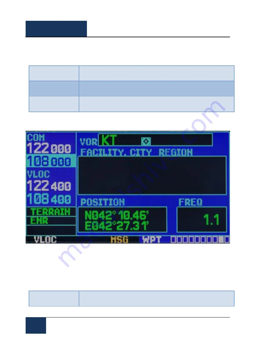
WPTvor Page 


Figure 21: WPTvor Page 

The  VOR  page  displays  the  code  name,  city,  region  /  country,  the  magnetic  variation,  latitude  and 
longitude for the selected VOR. The frequency is also displayed. 

NDBs may be selected by their identifier as described in the preceding pages 

(misplaced?)


The following symbols and abbreviations are used: 

FACILITY, CITY & 
REGION


Name of the city and region 

Summary of Contents for NS 430

Page 1: ...NS 430 DCS BELSIMTEK 1 FPL Navigation System NS 430 USER MANUAL...

Page 2: ...e information page of the instrument Quick setup for navigating to a selected destination from the current location Creation editing selection and activation of flight plans Creation of custom WPTs In...

Page 3: ...BELSIMTEK 3 Yours truly The NS 430 Development Team Website www belsimtek com DCS www digitalcombatsimulator com 2017 Belsimtek All trademarks and registered trademarks are the property of their respe...

Page 4: ...EDURE 12 SCREEN 14 LEFT SCREEN PANEL 14 LOWER SCREEN PANEL 14 SCREEN ALLOTMENT 14 PAGES 17 NAV PAGES 17 NAVdef Page 17 NAVmap page 19 NAVterrain Page 22 NAVcom page 23 NAVpos page 24 NAVsat page 25 NA...

Page 5: ...47 NRST PAGE GROUP 48 NRSTapt Page 49 NRSTint Page 50 NRSTndb Page 51 NRSTvor Page 52 NRSTuser Page 53 NRSTartcc Page 54 NRSTfss Page 55 NRSTspace Page 56 FPL PAGE GROUP 57 FPLact Page 57 FPLcat Page...

Page 6: ...DCS NS 430 6 GNS430 INSTRUMENT CONTROLS...

Page 7: ...gahertz frequency for the communications transciever COM or the VLOC receiver depending on which is currently selected by the cursor The small left knob is used to tune the kilohertz kHz value of the...

Page 8: ...the user to set or make changes to certain parameters and access additional functions The clear CLR button is used to delete information or clear set options Press and hold the button to immediately...

Page 9: ...NS 430 DCS BELSIMTEK 9 Lower Section Controls Figure 3 Lower section controls 1 CDI 2 OBS 3 MSG 4 FPL 5 PROC...

Page 10: ...point as active even after it is passed suspending automatic transition to the next waypoint Pressing the OBS button again returns the system to normal operation with automatic sequencing of waypoints...

Page 11: ...NS 430 DCS BELSIMTEK 11 Instrument Operations...

Page 12: ...reens on the first screen the user will have to press or rotate the power knob and will be prompted to to press ENT several times Afterwards the satellite status will be displayed on the screen and af...

Page 13: ...NS 430 DCS BELSIMTEK 13 Figure 5 Instrument Panel Self Test...

Page 14: ...y violation currently it is assumed that the GPS is always integral and no errors are present in the diagnostics Lower Screen Panel The device status is displayed on the lower section of the screen Na...

Page 15: ...rain WPTfreq AUXsetup1 NRSTndb NAVcom WPTapr AUXsetup2 NRSTvor NAVpos WPTarr NRSTuser NAVsat WPTdep NRSTartcc NAVvprof WPTint NRSTfss WPTndb NRSTspace WPTvor WPTuser In addition to the main blocks is...

Page 16: ...locks is carried out either at the end of any action or by holding the CLR button for 2 seconds Each of the main pages has an options menu allowing you to choose the configuration of the relevant page...

Page 17: ...indicate the current reception of satellites and define settings for vertical navigation NAVdef Page Figure 1 NAVdef Page The first page is the NAVdef page displayed as default This page can be quickl...

Page 18: ...erence The available options are as follows Bearing to destination BRG Distance to destination DIS Enroute safe altitude ESA Estimated time en route ETE Minimum safe altitude MSA Ground track TRK Cros...

Page 19: ...The top of the map will also show a window in which the indicator coordinates as well as the bearing and distance from your current position to the indicated position To select the panning function a...

Page 20: ...l be created at the location of the pointer before initialization of the DIRECT TO mode To display the menu options for the map page press the MENU button Available options Setup Map Measure Dist Data...

Page 21: ...er selectable fields on the right side on the map page There are 14 types of data including the bearing and distance to destination estimated time of arrival ground speed minimum safe altitude and tra...

Page 22: ...tude is received from GPS To Inhibit or Enable TERRAIN 1 Select the NAVter page and press MENU 2 Select Inhibit Terrain Enable Terrain using the large right knob 3 Press ENT TERRAIN will now be inhibi...

Page 23: ...to your point of departure To select the frequency list for the airport of departure or arrival 1 Press the smaller right knob to activate the cursor 2 Turn the smaller right knob to activate the air...

Page 24: ...ground speed and altitude The minimum safe altitude MSA can also be indicated on these fields MSA is the minimum recommended altitude within a 10 mile radius from your current position MSA is calculat...

Page 25: ...at the top of the page and the reference waypoint fields to default settings To restore factory settings 1 Press the MENU button to display the options menu for the position page 2 Rotate the large ri...

Page 26: ...o a target altitude and location This is useful when you want to descend to a certain altitude near the airport or up to a certain altitude before you reach the altitude of the route or destination po...

Page 27: ...in the vertical navigation page You can expect the following when using the vertical navigation function 1 One minute until the initial descent point the message Approaching VNAV Profile will appear...

Page 28: ...ded identifier then press ENT 6 To remove the flashing cursor press the small right knob After entering the WPT identifier all six pages of the airport will indicate information for the selected airpo...

Page 29: ...f airspace The following descriptions and abbreviations are used POSITION Latitude Longitude in degrees minutes or degrees minutes seconds MGRS and UTM UPS only degrees minutes are used in the current...

Page 30: ...unway surface and lighting system for the selected airport A map showing the boundaries of the runway and the surrounding area is also displayed on the runway page The map scale is shown in the lower...

Page 31: ...he airport runway page has an INFO window with the following information from top to bottom The following options are available for this page they are displayed when the MENU button is pressed Select...

Page 32: ...equencies and tune to a desired frequency on the list 1 Click on the small right knob to activate the cursor 2 Using the large and a small right knob enter the airport name or immediately press ENT 3...

Page 33: ...the window with a list of all available approaches for the selected airport Continue rotating the small right knob to select the desired approach 4 Press ENT to select 5 To remove the flashing cursor...

Page 34: ...STAR for the selected airport If there are multiple transitions or runways associated with the arrival procedure this information is also displayed To browse the list of available arrivals 1 Click on...

Page 35: ...procedures from the procedures page Select Next FPL Apt Not implemented in the current version Select Destination Apt Not implemented in the current version WPTdep Page Figure 18 WPTdep Page The airp...

Page 36: ...departure procedure for creating a new flight plan This action is identical to the procedure of downloading arrival procedures from the procedures page Select Next FPL Apt Not implemented in the curre...

Page 37: ...IS Distance from the nearest VOR in nautical miles land miles kilometers depending on the system configuration NEAREST VOR Nearest VOR ATTENTION The VOR displayed on the intersections page is the clos...

Page 38: ...degrees minutes seconds MGRS or UTM UPS FREQ The frequency in kHz WPTvor Page Figure 21 WPTvor Page The VOR page displays the code name city region country the magnetic variation latitude and longitud...

Page 39: ...0 allows you to store up to 1 000 user defined waypoints The user waypoint page displays the waypoint name up to five characters in length the identifier radial between two reference waypoints and the...

Page 40: ...firm the position 5 After the Create prompt appears press ENT To create a new user waypoint by entering its position latitude longitude 1 Follow steps 1 5 of the previous section 2 Use the small and l...

Page 41: ...to display the user waypoint page for a selected waypoint On this page you may view all the information that defines the user waypoint and its position To delete a user waypoint from the list 1 Select...

Page 42: ...the AUX page group AUX will appear in the lower right corner of the screen 6 Rotate the small right knob to select the desired AUX page AUXfpl Page Figure 23 AUXfpl page The flight planning page allo...

Page 43: ...nformation is accounted for automatically and the pilot has no need to enter it manually Density ALT TAS Winds Indicates the theoretical altitude at which the aircraft would fly in the presence of som...

Page 44: ...lable Checklists Provides up to 9 different checklists containing up to 30 items each Flight Timers provides access to timers with stopwatch and countdown functions as well as automatic recording of t...

Page 45: ...right knob 2 Rotate the large right knob to select the desired option then press ENT The following options are available Airspace Alarms Not implemented in the current version CDI Alarms allows you to...

Page 46: ...e When you approach this point at a specified distance up to 99 9 units you will receive a message displaying Arrival at WPT ID Units Mag Var allows you to configure the displayed data in standard or...

Page 47: ...options are available Display allows you to customize the display for optimal visibility under all conditions There is an automatic backlight that uses the built in photocell in the upper left part of...

Page 48: ...e scroll bar on the right side of the screen shows which part of the list can be seen at the moment The closest SUA page displays detailed information for the three closest special use air spaces The...

Page 49: ...the COM window and is activated with the C button To quickly set the recommended CTAF frequency from the nearest airport page 1 Select the nearest airport page as described above 2 Press the small ri...

Page 50: ...additional pages for the selected airport s waypoints including runway pages and communication frequencies turn the small right knob to display the additional waypoint pages NRSTint Page Figure 28 NRS...

Page 51: ...age 1 Select the nearest node page as described above 2 Press the small right knob to activate the cursor 3 Turn the large right knob to scroll through the list highlighting the communications frequen...

Page 52: ...y and can be used to quickly tune the VOR receiver to the closest VOR The selected frequency is placed in the reserve field of the VLOC window and is activated with the V button To quickly adjust the...

Page 53: ...R NRSTuser Page Figure 31 NRSTuser page The nearest USER WPT page displays the identifier symbol bearing and distance to the nearest VOR user waypoint within 200 miles of your current location To view...

Page 54: ...and is activated by the C button To quickly tune the recommended ARTCC frequency from the nearest ARTCC page 1 Select the nearest ARTCC page as described above 2 Press the small right knob to activate...

Page 55: ...the recommended frequency of FSS from the nearest FSS page 1 Select the nearest service station page 2 Press the small right knob to activate the cursor 3 Turn the large right knob to scroll through...

Page 56: ...ll appear Within 2nm of airspace will be displayed on the nearest SUA page 3 If you are within a 2 mile radius of the airspace and your current course will not lead you inside the airspace the message...

Page 57: ...allow you to create copy and edit flight plans FPLact Page Figure 35 FPLact Page The active flight plan page provides information and editing functions for flight plan 0 the flight plan currently in u...

Page 58: ...identifier If the waypoint is unique then a prompt will appear to select it If there are several such waypoints a message box and menu will appear 5 Press ENT 6 If there was more than one waypoint a m...

Page 59: ...eparture Selects a departure Change Fields Edits the displayed parameters Restore Defaults Restores the displayed parameters to their defaults FPLcat Page Figure 37 FPLcat page The flight plan catalog...

Page 60: ...s on the FLPact page To remove a waypoint from the current flight plan 1 Press the FPL button and rotate the small right knob to display the flight plan catalog 2 Press the small right knob to activat...

Page 61: ...flight plan 2 From the flight plan catalog page click the small right knob to activate the cursor turn the large right knob to highlight the flight plan that you want to delete then press MENU to dis...

Page 62: ...ate a direct path from your current location to your destination Navigation data on the various navigation pages will ensure flight control up until direct to mode is canceled or replaced by a new des...

Page 63: ...waypoint the waypoint name will be highlighted Press the DIRECT TO button to use the waypoint in the DIRECT TO page 4 Press ENT to activate DIRECT TO mode To select the nearest airport or other point...

Page 64: ...uld have procedures associated with them To select approaches departure or arrival procedures 1 Press the PROC button to display the procedures page 2 Rotate the large right knob to highlight Select A...

Page 65: ...complete approach to the destination airport in advance Later when vectored to final use the steps above to select Activate Vector To Final which activates the inbound course to the FAF Alternatively...

Page 66: ...Turn on the cursor by pressing the small right knob 3 Add the required number of points on the route by turning the small right knob to highlight the window for adding waypoints 4 When you are finish...

Page 67: ...and selecting the ATIS frequency from the list This frequency is placed in the reserve window Use the C button to make the ATIS frequency active 3 From the ATIS frequency you will learn that runway 03...

Page 68: ...the center to fly to MAP observing the minimum height specified for the approach 12 After crossing the MAP above the OBS will display SUSP indicating that the automatic approach waypoint sequencing w...

Page 69: ...ing the approach the active flight plan page will be displayed You can see the approach sequence by clicking on the small right knob and turning the big right knob Press the FPL button to return to th...

Page 70: ...arc approaches uses additional waypoints from the Jeppesen database to determine the arc These waypoints are displayed using the letter D at the beginning of the name of the waypoint followed by thre...

Page 71: ...en Make any necessary course adjustments for final approach from the FAF to MAP 10 10 After crossing the FAF the destination point becomes MAP runway 21 the runway edge Hold the needle in the center o...

Page 72: ...ch was activated with vector to final In this example we assume that the vectors of the control point will be perpendicular to the final course 1 Within the 30 mile radius of KFOE the G430 will transi...

Page 73: ...ch VOR DME RWY 25 in Palmdale CA KPMD and includes a return course 1 When you reach the initial approach fix PMD a warning message NEXT DTK 070 alerting you to your arrival at the waypoint will be sho...

Page 74: ...e OBS button as the G430 temporarily suspends waypoint sequencing This is normal during course from fix to altitude legs 3 Fly the outbound course making sure that the CDI arrow is in the middle The m...

Page 75: ...waypoint HFD VOR The desired course will depend on the ground speed and the distance from the HFD VOR 6 After pressing OBS the G430 will automatically sequence waypoints for the remaining leg of the...

Page 76: ...right corner of the screen will show the warning NEXT DTK about 210 11 After the CDI needle starts to move towards the center turn left at 210o the ILS course After the course to the FAF the CDI autom...

Page 77: ...ircraft is at a set distance from the waypoint This distance is set at setup page 1 Auto CDI scale selected The GNS has automatically reset the CDI scale upon execution of route navigation or approach...

Page 78: ...AVGAS Aviation Grade Gasoline AVTN Aviation BARO Barometric pressure BRG Bearing C V COM VLOC CAS Calibrated Airspeed CDI Course Deviation Indicator CLR Clear COM Communications tranciever CRSR Cursor...

Page 79: ...Precision DTK Desired Track EFF Efficiency ELEV Elevation ENDUR Endurance ENR Enroute ENT Enter EPE Estimated Position Error ESA Enroute Safe Altitude ETA Estimated Time of Arrival ETE Estimated Time...

Page 80: ...way ID Identifier Ig Imperial Gallons IND Indicated INT Intersection INTEG Integrity kph Kilometers per hour kt Knots LAT LON Latitude Longitude lb Pounds LCL local LFOB Leftover Fuel on board LOC Loc...

Page 81: ...ute Miles per hour mpm Meters per minute mps Meters per second MSA Minimum safe altitude MSG Message MSL Mean Sea Level mul Multicom NATNL National NAV Navigation NAVAID Navigation aid NDB Non directi...

Page 82: ...ed RNG Range RX Receive SID Standard Instrument Departure Sml Small SPD Speed SQ Squelch SRFC Surface STAR Standard Terminal Arrival Route SUA Special Use Airspace T Degrees true TAS True Airspeed TAT...

Page 83: ...wr Tower TX Transmit uni Unicorn UTC Coordinated Universal Time also GMT zulu VAR Variation VER Version VFR Visual Flight Rules VLOC VOR Localizer receiver VNAV Vertical Navigation VOL Volume VS Verti...

Page 84: ...DCS NS 430 84 PAGES BRG DEVELOPERS DEVELOPERS...

Page 85: ...cumentation Alexander Babichev Project Manager PROGRAMMERS Yury Nekrasov Instrument systems programming Yury Kochmarev Vyacheslav Kosach Instrument compatibility with DCS World Missions DESIGN AND AUD...

Page 86: ...Harin Customer Support QUALITY CONTROL Valery USSR_Rik Khomenok Lead Tester Ivan Frogfoot Makarov Tester Alexander BillyCrusher Bilievsky Tester Nikita Nim Opredelenkov Tester Oleg Dzen Fedorenko Tes...

Reviews: