background image

Software Options 

(continued)

12

8.2

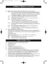
USB (Universal Serial Bus): HID (Human Interface Device) setup procedure
8.2.1

When the USB cable that comes with the UPS is first connected to a USB port on
your computer, the Windows

®

98 dialog called ADD NEW HARDWARE WIZARD

should appear automatically. (To display this dialog manually, you can choose the
Start button and then Settings to access the  Control Panel and then double-click
on ADD NEW HARDWARE. The USB cable should be connected already.)

8.2.2

THE ADD NEW HARDWARE WIZARD dialog box guides you through the 
installation process. Click on “Next”.

8.2.3

A dialog states "Windows will now search for any new Plug-and-Play devices 
on your system". Click “Next”.

8.2.4

A subsequent dialog gives you these options:
• Search for the best driver for your device (recommended).
• Display a list of all drivers in specific location, so you can select the driver 

you want. 

Please accept the recommended choice by clicking on “Next”.

8.2.5

The Wizard will then search your hard drive for a file called….\INF\hiddev.inf. 
This file contains all the information that Windows

®

98 needs to install the correct

device drivers.

8.2.6

At this point the wizard might ask for the Windows

®

98 CD-ROM. Place the 

CD in the CD-ROM drive and select OK.

8.2.7

The installation process will continue automatically until a dialog displays 
indicating that the drivers have been installed. Select the Finish button and 
your drivers are installed.

8.3

RS232 (Serial Interface) set-up procedure

Charge the UPS 2 – 4hours before installing the software. Connect the supplied RS232 
serial cable (excluding 325VA Series) to the UPS and connect the other end to a designated
port on the PC. Turn on the UPS, restart the PC and then place the supplied CD in the 
CD-ROM drive.

Installing the software.

(Note: These instructions assume D: is your CD-ROM drive. If not substitute the
appropriate drive letter for D:).

8.3.1

Click the Start button on your desktop task bar, and select Run.

8.3.2

Type D:\Windows\SETUP.EXE and click OK.

8.3.3

Follow the on screen instruction commands.

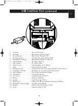
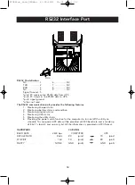
The computer interface port has the following characteristics:

1.

Plug-and-Play Support

2.

Hot Attachment

3.

USB Port Protection

4.

Self Powered

5.

1.5 MBits/sec Low-Speed USB Device

6.

Compliant With USB Specification Version 1.0

7.

Compliant With HID Specification Version 1.0

8.

Compliant With HID Power Device Class Version 1.0

9.

Display UPS Status Data: Voltage Out Of Range/Buck/Boost/Frequency Out Of Range/ 
Overload Over Charged/Over Temperature/Internal Fail/Shutdown Request/Shutdown 
Imminent Switch On/Off/Switchable/Tested Awaiting Power/Good/Beeper/Terminate
Charge/Terminate Discharge/Below Remaining Capacity-Limit/Remaining Time Limit-
Expired/Charging/Discharging/Fully Discharged/Need Replacement

10. 

Measurement Items: AC Input Voltage/AC Output Voltage/AC Input Frequency/AC Output
Frequency Battery Voltage/Battery Capacity/Temperature Percent Load 

11. 

Control Items: Turn On/Off Outlet/Schedule Shutdown/High/Low Transfer Voltage/Battery
Test Delay Before Shutdown/Delay Before Startup/Delay Before Reboot

USB Interface Port

P73220uk_Gold_UPSMan  27-05-2002  15:01  Page 12

Summary of Contents for F6C325-220V

Page 1: ...En P73220uk UPS Uninterruptible Power Supply User Manual P73220uk_Gold_UPSMan 27 05 2002 15 01 Page 1...

Page 2: ...the proper operation of the UPS come into question Please save or recycle the packaging materials The UPS shipping materials were designed with great care to provide protection from transportation re...

Page 3: ...nt Panel 6 Rear Panel 7 5 Installation 9 6 Operation 10 7 Alarm 11 8 Software Options 11 9 USB Interface Port 12 10 RS232 Interface Port 14 11 Battery Replacement 15 12 Troubleshooting 17 13 Storage 1...

Page 4: ...incur computer repairs lost data and downtime Solution A Belkin Uninterruptible Power Supply UPS with Automatic Voltage Regulation AVR Typical Stand by UPS units do not have AVR to increase the output...

Page 5: ...ible shock from touching two surfaces with different electrical grounds Connect the equipment to a three wire AC outlet two poles plus ground The receptacle must be connected to an appropriate circuit...

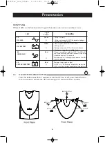
Page 6: ...s Battery output is drawing more power than the UPS can provide 4 3 REPLACE BATTERY Red Battery is too weak or bad If UPS is in On Battery mode this means the UPS is just testing the condition of the...

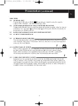
Page 7: ...sential equipment and reset the circuit breaker 4 10 BATTERY BACK UP OUTLETS Data sensitive equipment such as a computer monitor and external drive should be powered by these outlets Battery power is...

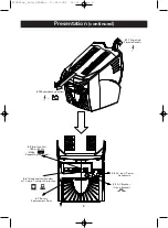
Page 8: ...tery Back up outlets 4 5 Interface Port USB or RS232 Depending on model 4 6 Telephone Fax Modem or 10 base T network Protection 4 7 Battery Replacement Door 4 9 AC Breaker Circuit Breaker 4 8 AC Input...

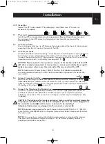
Page 9: ...Belkin Components for details of a local reseller 5 4 Connect Computer Interface Belkin Sentry Bulldog Shutdown Management Software and the USB or RS232 cable depending on model can be used with this...

Page 10: ...on when the UPS is supplying power to the connected loads The UPS can be utilised as a master on off switch for the protected equipment NOTE The UPS maintains the battery charge when in the off positi...

Page 11: ...Belkin Sentry Bulldog Shutdown Management Software or as stated in step 6 3 The alarm stops when the UPS returns to line normal operation 7 1 LOW BATTERY rapid alarm In backup mode when the battery en...

Page 12: ...up procedure Charge the UPS 2 4hours before installing the software Connect the supplied RS232 serial cable excluding 325VA Series to the UPS and connect the other end to a designated port on the PC T...

Page 13: ...n For Alarm 10 Voltage Sensitivity To Improve Transfer Time and Avoid Effect Of I P Distortion 11 Outlet Relay ON OFF Set Delay Time to Control Outlet Relay On Off 12 Next Shutdown Time To Next Schedu...

Page 14: ...condition 3 Monitoring inverter status 4 Monitoring UPS status 5 Monitoring the utility status 6 Providing the power switch function for the computer to turn on off the utility on schedule To save po...

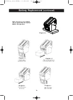
Page 15: ...e battery compartment cover down Diagram b 11 1 3 Grasp the battery and slide it partially out Then grab the battery firmly and remove the battery wires will disconnect as the battery is pulled out Di...

Page 16: ...contact Belkin Components Diagram a Diagram b Slide the battery compartment cover Diagram d Slide the battery back in Avoid pinching the wires Diagram c Slide the battery partially out Diagram e Slid...

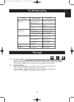
Page 17: ...g the power cord Replace the breaker Normal condition Recharge the UPS at least 4 hours Remove some unnecessary loads Replace battery Remove the non critical loads Replace battery 13 0 Storage Conditi...

Page 18: ...ad Type Protection Automatic self test and discharge protection replace battery indicator Typical Recharge Time 4 hours to 90 of full capacity Sealed maintenance free lead acid BATTERY PHYSICAL ALARM...

Page 19: ...load Type Protection Automatic self test and discharge protection replace battery indicator Typical Recharge Time 4 hours to 90 of full capacity Sealed maintenance free lead acid BATTERY PHYSICAL ALAR...

Page 20: ...SET FORTH ABOVE ARE EXCLUSIVE IN LIEU OF ALL OTHERS WHETHER ORAL OR WRITTEN EXPRESSED OR IMPLIED BELKIN SPECIFICALLY DISCLAIMS ANY AND ALL IMPLIED WARRANTIES INCLUDING WITHOUT LIMITATION WARRANTIES O...

Reviews: