background image

13

OmniViewIP 5216K/5232K

sections

table of contents

1

3

4

5

6

2

InsTallaTIOn

setting the IP address

By default, the Switch boots with an automatically assigned IP address 

from a DHCP (Dynamic Host Configuration Protocol) server on the 

network. The DHCP server provides a valid IP address, gateway 

address, and subnet mask.

You can identify the IP address from the OSD at the local position. You 

can set the IP address locally via the OSD where there is no DHCP 

server as follows:

1. 

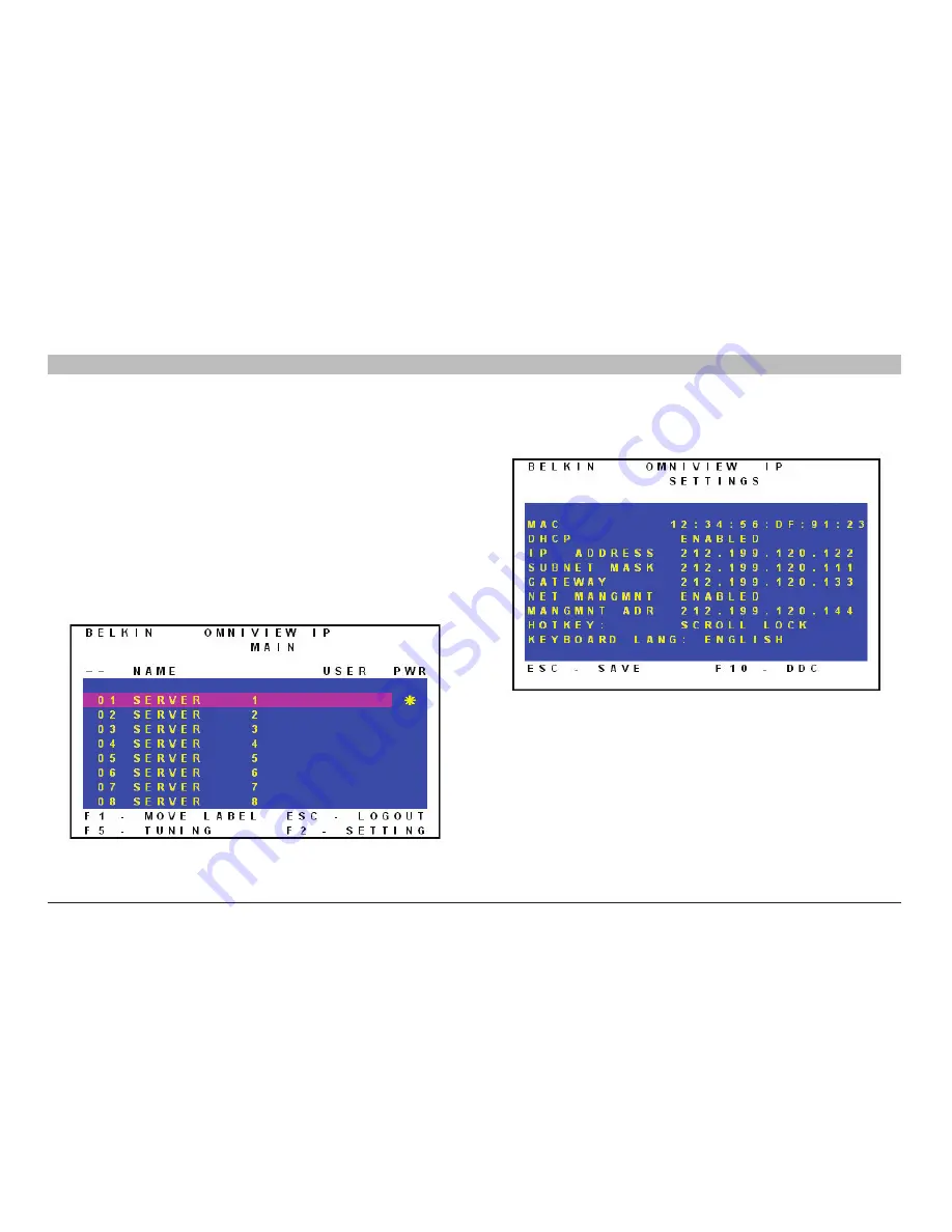
From the local keyboard, press “Scroll Lock”. The OSD Main 
window appears (see Figure 10). 

2. 

Press “F2”. The Settings window appears (see Figure 11). 

In the Settings window, navigate downward using the Tab key. At the 

bottom of the window, press “Tab” to go to the top of the window. 

Change settings by typing in the selected area or by pressing the space 

bar—whichever is relevant.

Figure 10 OSD Main window

Figure 11 Settings window

Summary of Contents for F1DP216G

Page 1: ...OmniViewIP 5216K 5232K User Manual PM00020 F1DP2XXG OmniView is a registered trademark of Belkin International Inc ...

Page 2: ...ings 23 Security SSL Certificate 24 Maintenance Switch Upgrade 24 Maintenance SIM Upgrade 25 Restore Factory Settings 25 Set Time and Date 26 Back Up and Restore 26 Saving Changes and Logging Out 27 1 Introduction 1 Key Features 2 System Contents 4 System Requirements 4 Terminology 5 Unit Display Diagrams 6 LED and button table 6 Connector table 6 2 Installation 7 Pre Installation Guidelines 7 Avo...

Page 3: ...ct Registration 50 Information 51 4 Remote Access 28 Accessing a Target Server 28 The toolbar 29 Switching to a different server 29 Changing the performance settings 29 Adjusting the video settings 30 Refresh 30 Manual video adjust 31 Auto video adjust 32 Keyboard key sequences 32 Synchronizing mouse pointers 34 Aligning the mice pointers 34 Manual settings 36 Calibrating mice pointers 38 Adjustme...

Page 4: ... more efficiently reducing server downtime and service costs in mission critical environments Belkin s distinctive technology provides IT professionals Immediate video synchronization allowing access through the entire boot sequence when troubleshooting is most critical Immediate video display and keyboard output to intercept systems at their earliest status upon power up or reboot Instantaneous a...

Page 5: ... the LAN WAN or Internet using Firefox or Microsoft Internet Explorer Out of Band BIOS Level Access The Switch allows you to remotely access the basic input output system BIOS of your servers to make changes and perform reboots regardless of network connectivity or server condition User Friendly Interface The web based interface allows you to set up and change the Switch s functions quickly and ea...

Page 6: ... data transferred over the Internet The data communication is also protected with AES 256 bit encryption Scalable Centralized Management Additional Switches can be added as your data center grows and the entire inventory can be managed under the Belkin Central Access Appliance 5000HQ This is ideal for corporations operating servers at multiple sites such as testing labs campuses branch offices and...

Page 7: ...and above USB server interface module required Servers PS 2 and USB computers servers VGA SVGA or XGA monitors Keyboards and Mice USB compatible Monitors CRT and LCD with VGA SVGA or XGA monitors Remote Client Browser The Switch may be accessed remotely over a TCP IP connection from computers using the following web browsers and OS platforms Windows Microsoft Internet Explorer 6 0 and above with A...

Page 8: ...mance of your video These Cables offer the highest quality possible to ensure optimal data and video transmission Belkin UTP Patch Cables A3L791 XX YYY CAT5e A3L850 XX YYY FastCAT 5e A3L980 XX YYY CAT6 Terminology Below are some terms and their meanings used in this guide Term Meaning Target server The computers servers that are accessed remotely via the Switch Client computer The PC running a rem...

Page 9: ...When unit is available for use Link Blinking Green Unit is connected to the network Power Power Indicator Figure 2 OmniView IP 5232K Switch rear view Connector table Connector Function Local Console Connect a keyboard video and mouse to operate the Switch locally Serial 1 Connect any serial device Serial 2 Connect any serial device LAN Connect to 10 100Mb Ethernet Yellow LED illuminates when conne...

Page 10: ...closed or multiunit rack assembly Install the equipment in an environment compatible with the maximum rated ambient temperature Reduced airflow Install the equipment in a rack in such a way that the amount of airflow required for safe operation is not compromised Leave a gap of at least 5cm 2 inches on each side of the Switch Mechanical loading Mount the equipment in the rack in such a way that a ...

Page 11: ...possible positions see Figure 3 Figure 3 Bracket positions Place the brackets toward the front of the unit so that the unit can be mounted front facing or place the brackets toward the rear of the unit so that it can be mounted rear facing on the back of a rack Figure 4 illustrates the bracket connected for rear facing Screw the bracket to the Switch using the screws provided Figure 4 Bracket conn...

Page 12: ... of Contents 1 3 4 5 6 2 INSTALLATION Connecting the System Figure 5 Switch s system overview LAN WAN Local User OmniView IP 5216K 5232K Switch PS 2 USB and Sun Servers TCP IP Remote User 1 CAT5 Cables Server Interface Modules Remote User 2 ...

Page 13: ...ed to the Switch via the appropriate SIM using CAT5 cables in a star configuration No external power is needed at the remote SIMs The SIMs draw their power from the computer s keyboard port PS 2 SIM or from the USB port USB SIM The figures below illustrate the SIM PS 2 and USB Figure 6 USB SIM2 part no F1DP101A AU Figure 7 PS 2 SIM part no F1DP101A AP ...

Page 14: ... port 4 Connect the video connector to the computer s VGA port 5 Power on the server Connecting a USB SIM The USB SIM supports Windows 2000 and later Sun SGI and all modern Linux distributions The connections for USB SIM are exactly the same Figure 9 illustrates the USB SIM and its connections To connect the USB SIM 1 Connect the video connector to the server s VGA port 2 Connect the USB connector...

Page 15: ... steps above for each computer Connecting the local console To operate the system locally connect a local console to the Switch 1 Connect the monitor s cable to the Switch s console monitor port 2 Connect the keyboard s cable to the Switch s console keyboard port 3 Connect the mouse s connector to the Switch s console mouse port Connecting the power supply 1 Using the power cord provided connect t...

Page 16: ...dress from the OSD at the local position You can set the IP address locally via the OSD where there is no DHCP server as follows 1 From the local keyboard press Scroll Lock The OSD Main window appears see Figure 10 2 Press F2 The Settings window appears see Figure 11 In the Settings window navigate downward using the Tab key At the bottom of the window press Tab to go to the top of the window Chan...

Page 17: ... is disabled Recommended You can assign a fixed IP address to the Switch Consult your network administrator regarding the use of the DHCP When DHCP is disabled enter the IP Address Subnet Mask and Gateway as given by your network administrator Once the IP address is satisfactory log in to the web interface to complete the configuration as explained in the next section Network parameters can also b...

Page 18: ...ight click the Internet Explorer icon on the task bar and select Run as administrator See figure below SSL certificate notes When first connecting two browser security warnings appear Click Yes to proceed The first warning disappears upon the first Switch client installation when Belkin s root certificate is installed On first connection install the Belkin certificate and ActiveX control You must ...

Page 19: ...t administrator user name admin and password SMBremote case sensitive 4 Press Enter The web interface opens at the Targets page see Figure 14 5 Bookmark the page for easy reference Figure 14 Targets page By default an administrator can access all connected Targets so they all appear on the Targets page Columns Server Name The server name can be changed in the configuration settings to give the ser...

Page 20: ...the menu click Configuration The Network Configuration page including the Configuration menu appears Network Configuration Consult your network administrator for the network settings if necessary Device Name Type a name for the Switch TCP Ports Choose any three TCP ports between ports 800 to 65535 When the Switch is a standalone system the ports do not have to be consecutive The port numbers can b...

Page 21: ...5000HQ is a centralized IP based system for secure control of servers and network devices power and user administration in the datacenter environment The 5000HQ combines out of band KVM via IP access with modern IT standards and requirements It is the most comprehensive remote server maintenance solution available in the market today Enable OmniView IP 5000HQ Check this option to allow the Switch ...

Page 22: ...ministrator has unrestricted access to all windows and settings and can take over any active session An administrator can change the name and password and target server permissions of all users User A user can access control permitted target servers but cannot use the advanced mouse settings A user has no access to the web configuration interface View only View only can view the screen of the curr...

Page 23: ...sers The Permission column shows the user level Administrator User and View Only The Status column shows whether the user is blocked or unblocked explained in the Blocking a user section Editing a user To edit a user 1 Select the user from the user drop down menu 2 You can now change all the parameters user name permission password and blocking status see the Blocking a user section 3 Click The ch...

Page 24: ...gure 17 2 In the Server Name section change the name of the connected servers by selecting the server name and typing a new name Click to save changes Administration Serial Settings Where you have a serial device connected to the system you must configure the serial RS232 settings To do so From the menu click Serial Settings The Serial Settings page will appear see Figure 18 Figure 17 Switch Confi...

Page 25: ...each user separately To do so 1 From the menu click Server Access List The Access List Configuration window will appear see Figure 19 2 Select a user from the user drop down menu 3 Check the target servers the user can access according to his or her access permissions To select all target servers click 4 Click to save the selection 5 Repeat the steps above for additional users Figure 19 Server Acc...

Page 26: ...acter as follows _ Must not include the user name Must not include the user name Check the box to enable the high security password policy If left unchecked the standard security policy applies OSD password enabled For the local user access to the OSD can be password enabled or disabled default with the option of a standard or high security level of password as explained above Select the check box...

Page 27: ...pgrade window will appear showing the current firmware version see Figure 22 Certificate File Browse to locate the cer file ssl format Private Key File Browse to locate the private key file pem format Key Password Type the key password Click The certificate installs The device restarts automatically 1 Locate and upload the firmware file 2 Verify the current and uploaded version of the firmware 3 C...

Page 28: ...sion of the firmware by clicking 4 Locate and upload the firmware file 5 Press and the firmware upgrades Figure 23 SIM Upgrade Figure 24 Restore factory settings Restore Factory Settings You can restore the Switch to the factory settings This restores the original Switch parameters resetting all the information added by the administrators including network settings servers users and passwords etc ...

Page 29: ...e Date and Figure 25 appears Figure 26 Backup Restore Figure 25 Set Time Date Type the appropriate parameters Back Up and Restore You can back up all configuration data to restore it at a later date To do so From the menu select Backup Restore and Figure 26 appears To back up the configuration data click to save the file To restore the configuration data browse to locate the file and press The dev...

Page 30: ...ration changes click the relevant button on the current page This could be or just To restart the Switch press To exit the Configuration menu and close the session click Only one administrator can log in to the Configuration area at a time After the idle timeout see the Security Settings section on page 23 the session terminates ...

Page 31: ...ure 27 Remote Console window On the remote console you have the following Server name The currently accessed server identity can be checked any time by looking at the Server name on the Internet Explorer title bar Toolbar icon This is the minimized toolbar from which you switch and configure the system Remote Session icon Hold the mouse over the icon to view information about current server connec...

Page 32: ...ch system tray icon or Press F9 To display the toolbar repeat the action above Also see page XX Switching to a different server To connect to a different server 1 From the toolbar click or right click A list of available servers appears The currently connected server is highlighted in bold 2 Click the desired server name The screen of the selected server appears Changing the performance settings Y...

Page 33: ...lors Medium is recommended when using a standard Internet connection High For optimal performance when working on a LAN select High This gives a low compression and high colors 16 bit Custom You can choose your own compression and color levels Click OK The screen of the last accessed target server appears Adjusting the video settings To change the video settings From the toolbar click You have the...

Page 34: ...to this frame Brightness Contrast Use the scales to adjust the brightness and contrast of the displayed image Move the sliders to change the displayed image Click in the area of the sliders for fine tuning For the following controls choose the appropriate measurement Horizontal Offset Defines the starting position of each line on the displayed image Vertical Offset Defines the vertical starting po...

Page 35: ... Keyboard key sequences Click A list of defined keyboard sequences appears When clicked these transmit directly to the target server and will not affect the client computer For example select Ctrl Alt Del to send this 3 key sequence to the target server to initiate its shutdown login process To add a keyboard sequence Click Add Remove The Special Key Manager box appears see Figure 30 To add a pred...

Page 36: ...e in the Label field 3 Click Start Recording and click inside the main window 4 Press the desired keys The key sequence appears in the area provided 5 Click Stop Recording 6 Click OK Figure 31 Add Special Key Dialog box To edit a key sequence 1 From the Special Key Manager Dialog box select the desired key 2 Click Edit 3 Click Start Recording 4 Press the desired keys The keys appear in the area pr...

Page 37: ...ows 2000 XP 2003 Server Vista 1 Go to the Windows Control Panel 2 Select Mouse and then navigate to the Pointer Options tab 3 Make sure the pointer speed slider is in the exact center between Slow and Fast Warning Before synchronizing mouse pointers make sure that mouse acceleration is disabled on all attached target servers explained below otherwise mouse synchronization may not work Note for Win...

Page 38: ...avigate to the Motion tab 3 Set the Acceleration to five clicks from left 4 Set the Sensitivity to three clicks from left 5 Set the Threshold to two clicks from left When accessing the target server the mice may appear at a distance to each other To align the mouse pointers From the toolbar click Align or press left Ctrl M simultaneously The mice will align ...

Page 39: ...click Manual Settings The Mouse Settings dialog box appears see Figure 32 Figure 32 Mouse Settings Dialog box 2 Select the target server s operating system and click OK Instructions and sliders appear Note You must do this configuration on every port 3 Follow the instructions and set any relevant sliders to the same values as set in the target server s Mouse Properties window 4 Check USB if the SI...

Page 40: ... reset sequence for a local mouse Setting it incorrectly may lead to a jumpy or non operational local console mouse after a remote user disconnects it from the Switch Max Rate This defines the maximum mouse report rate For Sun Solaris the default value is 20 in order to support older Sun versions If a 2 button mouse older mice without wheel capability most of the touch pads trackballs or integrate...

Page 41: ...ch saves this alignment so calibration is only needed once per target server If the video noise level is above zero calibration may not work Go to Video Adjustment and try to eliminate the noise by pressing Auto video adjust and or adjusting the bars in manual video adjust Then perform the mouse calibration Note If the mouse settings on the target server were ever changed you must synchronize mous...

Page 42: ...igure 35 Hide Toolbar Check this option to hide the toolbar from the next reconnection onward To toggle the toolbar on and off press F9 or double click the system tray icon Full Screen Mode Check this option to make the remote session screen appear in full screen mode from the next reconnection onward To toggle the full screen mode on and off press F11 also see the next section Virtual Media Click...

Page 43: ...nect a separate USB cable to VM ports 1 and 2 located on the back of the Switch and match to the corresponding servers connected to server ports 1 and 2 2 Select the device to be mounted and click Mount A remote device warning should appear 3 Click OK The device mounts onto the target server and appears as a removable or CD DVD drive of the target server It also appears in the Mounted Drives secti...

Page 44: ...en client session only This means if the remote client session disconnects the mounted drives will be automatically dismounted from the target server Maximum data transfer speed of the virtual media doesn t exceed 5 0Mbps Only drives identified by the client s operating system as drives with removable storage can be mounted as virtual media Many USB attached hard disks identify themselves to the o...

Page 45: ...disappears You are in full screen mode To exit full screen mode Press F11 or place the mouse at the top of the window to display the Internet Explorer toolbar and click the Restore button Note Full screen mode can also be activated from the toolbar menu see page 29 Disconnecting the remote session To disconnect the session click on the toolbar The Login page appears You can re log in or close the ...

Page 46: ...the number of events that will appear on each page 10 40 Downloading the log You can download and save the log To do so click and save as a csv file The file can be viewed using Microsoft Excel or compatible software Clearing the log To clear the log click A prompt appears asking if you first want to save the log Figure 36 Password Figure 37 Events log Type a new password according to the password...

Page 47: ...ppears see Figure 38 The Pwr column indicates the server is powered on Navigating the OSD Main window To navigate up and down use the up and down arrow keys To exit the OSD press Esc Selecting a computer To select a computer 1 Navigate to the desired computer line Or type the 2 digit port number of the desired computer 2 Press Enter The selected computer is accessed A confirmation label appears sh...

Page 48: ...eo tuning may be required if the distance between the Switch and the server is between 50 and 100 feet You can tune the image of any computer screen from the Main window To adjust the screen image 1 Navigate to the computer line you wish to adjust 2 Press F5 The screen image of the selected computer appears together with the Image Tuning label see Figure 39 Figure 39 Image Tuning label 3 Adjust th...

Page 49: ...hot key options following Ctrl Ctrl left Ctrl key only Ctrl F11 left Ctrl key only Print Screen Press the space bar to toggle between options To display the OSD in the future press the new hot key KEYBOARD LANGUAGE Press the space bar to toggle between the language options It can be changed to French or German In the Settings window navigate downward using the Tab key At the bottom of the window p...

Page 50: ...t the DDC information Press F10 Please wait flashes a few times and disappears The monitor s DDC information is sent to all SIMs Updating the DDC information Update the DDC information in any of the following circumstances When replacing the monitor connected to the Switch When adding a new SIM to the system When reconnecting an existing SIM that was temporarily used in a different system To updat...

Page 51: ... Security 128 bit SSL encryption 256 bit AES encryption Connections Ethernet RJ45 10 100bps auto sensing Serial RJ45 x 2 Local KVM Connection Screen HDD15 Keyboard Mouse 2 USB Servers RJ45 Weight 2 343kg 5 165 lbs Dimensions H x D x W 44 x 270 x 431mm 1 7 x 10 6 x 17 in Power Input 100 240VAC 0 8A 50 60Hz Operating Temperature 0 C to 40 C 32 F to 104 F Storage Temperature 40 C to 70 C 40 F to 158 ...

Page 52: ...dditional information Video Resolution and Refresh Rates Hz 56 60 65 66 70 72 73 75 76 85 86 640x480 x x x x x x 720x400 x x 800x600 x x x x x x 1024x768 x x x x x x x 1152x864 x 1152x900 x x 1280x720 x 1280x768 x x 1280x960 x x 1280x1024 x x x x x 1600x1200 x x x x x ...

Page 53: ...ual Feedback Your feedback is very important to help us improve our documentation Please email any comments to techsupp belkin com Please include the following information Manual name part number and P number Product Registration You may register your product online by going to https www belkin com registration This will assist Belkin in contacting you regarding important information regarding the...

Page 54: ... International Inc of 501 West Walnut Street Compton CA 90220 declare under our sole responsibility that the products F1DP216G F1DP232G to which this declaration relates This equipment has been tested and found to comply with the limits for a Class A digital device pursuant to Part 15 of the FCC Rules These limits are designed to provide reasonable protection against harmful interference when the ...

Page 55: ...n design assembly material or workmanship What the period of coverage is Belkin warrants the Belkin product for two years What will we do to correct problems Product Warranty Belkin will repair or replace at its option any defective product free of charge except for shipping charges for the product Belkin reserves the right to discontinue any of its products without notice and disclaims any limite...

Page 56: ...e purchaser may have How state law relates to the warranty THIS WARRANTY CONTAINS THE SOLE WARRANTY OF BELKIN THERE ARE NO OTHER WARRANTIES EXPRESSED OR EXCEPT AS REQUIRED BY LAW IMPLIED INCLUDING THE IMPLIED WARRANTY OR CONDITION OF QUALITY MERCHANTABILITY OR FITNESS FOR A PARTICULAR PURPOSE AND SUCH IMPLIED WARRANTIES IF ANY ARE LIMITED IN DURATION TO THE TERM OF THIS WARRANTY Some states do not...

Page 57: ...620 Europe www belkin com support Belkin B V Boeing Avenue 333 1119 PH Schiphol Rijk The Netherlands 31 0 20 654 7300 31 0 20 654 7349 fax Belkin Ltd 4 Pioneer Avenue Tuggerah Business Park Tuggerah NSW 2259 Australia 61 0 2 4350 4600 61 0 2 4350 4700 fax 2009 Belkin International Inc All rights reserved All trade names are registered trademarks of respective manufacturers listed Windows Windows V...

Reviews: