Installation BAT-R
Release 17 12/2020
43
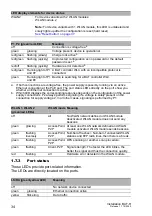
Remove the terminal connector from the device.
Connect the protective conductor with the clamp.
Fasten the wires in the terminal block by tightening the terminal screws.
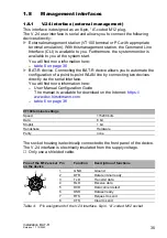
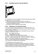
Connect the wires according to the pin assignment on the device with the
clamps.
Fasten the wires in the terminal block by tightening the terminal screws.
2.5.3
Supply voltage with the characteristic value W
(24 V DC)
Note:
For devices with 2 WLAN modules, the option of suppling power via
PoE is unavailable.
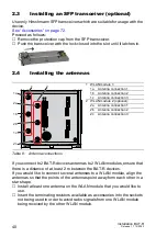
Figure 4: Supply voltage with characteristic value W (24 V DC): 2-pin terminal block
with screw locking
AC voltage
Rated voltage range AC:
110 V AC ... 230 V AC,
50 Hz ... 60 Hz
Voltage range AC incl.
maximum tolerances:
88 V AC ... 265 V AC,
47 Hz ... 63 Hz
+/L
Outer conductor
-/N
Neutral conductor
Protective conductor
Type of the voltages
that can be
connected
Specification of the supply
voltage
Pin assignment on the device
DC voltage
Rated voltage DC:
24 V DC
Voltage range DC incl.
maximum tolerances:
16.8 V DC ... 32 V DC
+
Plus terminal of the supply voltage
−
Minus terminal of the supply
voltage
Table 11: Supply voltage with characteristic value W (24 V DC): type and
specification of the supply voltage, pin assignment on the device
Type of the voltages
that can be
connected
Specification of the supply
voltage
Pin assignment on the device
Table 10: Supply voltage with characteristic value K (60 V DC ... 250 V DC /
110 V AC ... 230 V AC, 50 Hz ... 60 Hz): type and specification of the
supply voltage, pin assignment on the device


