background image

25

iTX Playout Appliance 2

Installation and Service Manual

Replacing the Graphics Card

To remove and replace the graphics card:

1 Power down the system and remove power from the unit.

2 Disconnect all of the cables from the unit’s rear panel.

3 Remove the unit from the rack and place on a solid, flat surface.

4 Remove the top cover from the chassis.

5 On the right-side of the chassis’ rear panel, lift the two small levers   to unlock the card 

bracket from the chassis.

If your chassis model does not have these levers, remove the four screws (2 on rear, 2 on 
top) that secure the card bracket to the frame. 

6 If the graphics card is a NVIDIA Quadro P4000, unplug the graphics card cable that is 

connected to the 

GPU PWR

 connector on the chassis’ motherboard.

7 Carefully lift the bracket upwards to remove the entire bracket from the chassis. The 

graphics card, video card and network adapter card remain attached to the bracket.

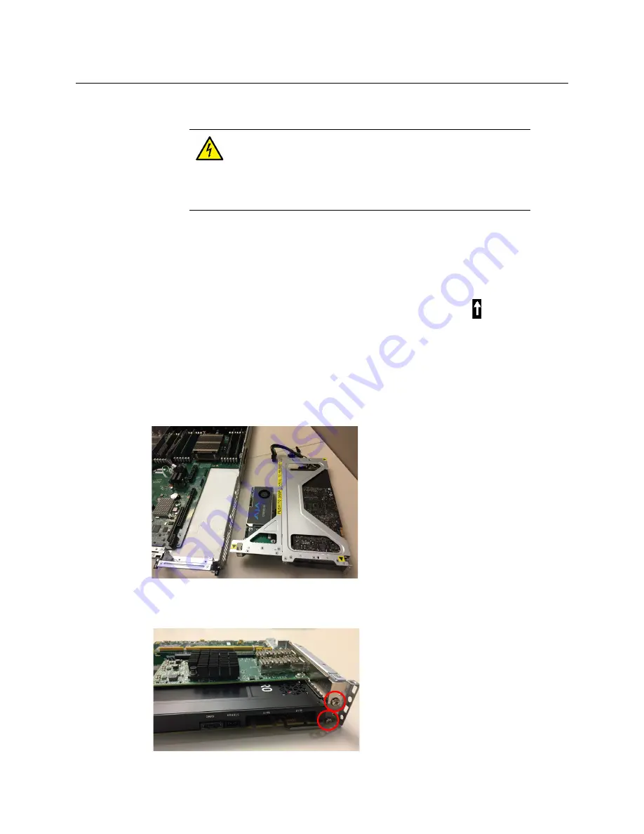
8 Place the bracket on a flat surface so that the graphics card is in the lower portion of the 

bracket (see image below). Remove the 2 screws that secures the network adapter card 
and the graphics card to the bracket.

WARNING


- Power Disconnection

The system must be disconnected from all sources of power and the 
power cord removed from the power supply module(s) before 

accessing the chassis interior to install or remove system components. This 
unit has more than one power supply connection. All connections must be 
removed to de-energize the unit.

Summary of Contents for GRASS VALLEY iTX Playout Appliance 2

Page 1: ...INSTALLATION AND SERVICE MANUAL Revision 1 M958 9002 301 2018 08 22 ITX PLAYOUT APPLIANCE 2 GVSP 3TB WIN 2IO GVSP 3TB WIN 2 2IO GVSP 3TB WIN 4IO GVSP 3TB WIN 8IO GVSP 4TB WIN 8IO ...

Page 2: ...iance 2 to use their product manuals for their own internal business use Manuals for Grass Valley products may not be reproduced or transmitted in any form or by any means electronic or mechanical including photocopying and recording for any purpose unless specifically authorized in writing by Grass Valley A Grass Valley manual may have been revised to reflect changes made to the product during it...

Page 3: ... ground prior to making any other equipment connections Identifies an external protective grounding terminal which may be connected to earth ground as a supplement to an internal grounding terminal Indicates that static sensitive components are present which may be damaged by electrostatic discharge Use anti static procedures equipment and surfaces during servicing Indicates that the equipment has...

Page 4: ...uid or aerosol cleaners use only a damp cloth Dangerous voltages may exist at several points in this equipment To avoid injury do not touch exposed connections and components while power is on High leakage current may be present Earth connection of product is essential before connecting power Prior to servicing remove jewelry such as rings watches and other metallic objects To avoid fire hazard us...

Page 5: ...this equipment Electrostatic Discharge ESD Protection Electrostatic discharge occurs when electronic components are improperly handled and can result in intermittent failure or complete damage adversely affecting an electrical circuit When you remove and replace any card from a frame always follow ESD prevention procedures Ensure that the frame is electrically connected to earth ground through the...

Page 6: ... l équipement cette tension peut être suffisante pour constituer un risque de décharge électrique Avertit l utilisateur l opérateur ou le technicien de maintenance que des instructions importantes relatives à l utilisation et à l entretien se trouvent dans la documentation accompagnant l équipement Invite l utilisateur l opérateur ou le technicien de maintenance à prendre note du calibre du fusibl...

Page 7: ...ts de câbles afin de ne pas endommager les connecteurs Coupez l alimentation avant de nettoyer l équipement Ne pas utiliser de nettoyants liquides ou en aérosol Utilisez uniquement un chiffon humide Des tensions dangereuses peuvent exister en plusieurs points dans cet équipement Pour éviter toute blessure ne touchez pas aux connexions ou aux composants exposés lorsque l appareil est sous tension L...

Page 8: ... modules d alimentation auto adaptables vérifiez la configuration de chacun des modules d alimentation avant de les mettre sous tension Assurez une ventilation adéquate Pour éviter toute surchauffe du produit assurez une ventilation de l équipement conformément aux instructions d installation N utilisez pas l équipement si vous suspectez un dysfonctionnement du produit Faites le inspecter par un t...

Page 9: ...vérifiez la polarité et ne remplacez la pile que par une pile du même type recommandée par le fabricant Mettez les piles usagées au rebut conformément aux directives du fabricant Avant de vous défaire de l équipement assurez vous d avoir lu l appendice Disposal and Recycling Information Précautions pour les écrans LCD et TFT Regarder l écran pendant une trop longue période de temps peut nuire à vo...

Page 10: ...requency electromagnetic field immunity EN 61000 4 4 Electrical fast transient immunity EN 61000 4 5 Surge transient immunity EN 61000 4 6 Conducted disturbances immunity EN 61000 4 8 Power frequency magnetic field immunity EN 61000 4 11 Voltage dips short interruptions and voltage variations immunity Note This equipment has been tested and found to comply with the limits for a Class A digital dev...

Page 11: ... the iTX Playout Appliance 2 13 3 Configuring the iTX Playout Appliance 2 15 Configuring Windows and System Settings 15 Configuring iTX GVSP 3T WIN 2IO and GVSP 3TB WIN 2 2IO 17 Configuring iTX GVSP 3T WIN 4IO GVSP 3TB WIN 8IO GVSP 4TB WIN 8IO 19 4 Servicing the iTX Playout Appliance 2 21 Removing Power from the System 21 Removing and Replacing the Bezel 22 Removing the Chassis Cover 23 Replacing ...

Page 12: ...xii Table of Contents ...

Page 13: ...vides information about the different models of iTX Playout Appliance 2 and the physical characteristics of the product including system specifications and chassis components Summary About the iTX Playout Appliance 2 2 System Specifications 2 Front Panel Components 5 Rear Panel Components 7 Note Additional iTX system documentation can be downloaded from the Documentation Library on the Grass Valle...

Page 14: ...XG Inside since it does not have a GPU GVSP 3TB WIN 4IO 1RU iTX SD HD Playout Appliance fitted with a single 4 I O SDI video card This unit is equipped with a GPU to support XG Inside not licensed GVSP 3TB WIN 8IO 1RU iTX HD Playout Appliance fitted with a single 8 I O SDI video card This unit is equipped with a GPU to support XG Inside not licensed GVSP 4TB WIN 8IO 1RU iTX Playout Appliance 2 fit...

Page 15: ...orvid 88 card with up to 8 SDI I Os on DIN 1 0 2 3 connectors GVSP 4TB WIN 8IO 1 AJA Corvid 88 card with up to 8 SDI I Os on DIN 1 0 2 3 connectors Graphics Card GVSP 3TB WIN 2IO NVIDIA Quadro P2000 GVSP 3TB WIN 2 2IO Not equipped with a graphics card GVSP 3TB WIN 4IO NVIDIA Quadro P2000 GVSP 3TB WIN 8IO NVIDIA Quadro P2000 GVSP 4TB WIN 8IO NVIDIA Quadro P4000 Power consumption GVSP 3TB WIN 2IO GV...

Page 16: ...dded Systems GVSP 4TB WIN 8IO Microsoft Windows Server 2012 R2 for Embedded Systems Onboard controllers ports USB 3 0 ports 2 front 2 rear Dedicated IPMI LAN port 1 COM port 1 VGA monitor port 1 Only used on GVSP 3TB WIN 2 2IO Network I O Chassis 10 Gigabit Ethernet ports 2 Network Adapter Card 25 Gigabit Ethernet ports 2 SFP28 Video card I O Corvid LP 3 BNC Output Input Reference Corvid 44 5 DIN ...

Page 17: ...and rear of the chassis for easy system location in large stack configurations The Power button is the main power switch used to power on off the iTX Playout Appliance 2 unit Note that turning off system power with this button removes the main power but keeps standby power supplied to the system The Information light alerts operators to specific system states Continuous red Overheat condition Blin...

Page 18: ...le drive can be replaced without having to stop the system or remove power from the unit Managing the RAID Arrays on the iTX Playout Appliance 2 The Intel Rapid Storage Technology RST software is used to manage RAID arrays on the iTX Playout Appliance 2 This software is pre installed and running on the unit When operating properly the Intel RST icon in the Windows system tray appears as a hard dri...

Page 19: ...wer supply units as well as the appliance s input and output connectors The following diagrams identify the rear panel components of the different iTX Playout Appliance 2 models Fig 1 1 Rear panel components of the GVSP 3TB WIN 2 Fig 1 2 Rear panel components of the GVSP 3TB WIN 2 2IO Fig 1 3 Rear panel components of the GVSP 3TB WIN 4IO and GVSP 3TB WIN 8IO ...

Page 20: ...TB WIN 8IO with a Corvid 88 card Each card s DIN connectors are labeled with a number except for one which is R for Reference The SDI video card s input and output connections are determined by the intended playout channel type e g Single channel Dual channel Simulcast etc See About Playout Types in the Output Server 2 Channel Configuration Guide for more information Use the following tables to de...

Page 21: ... channel Ch A Output Main Ch A Input Main Ch A Output Sec Ref Input 4K Single channel Ch A Output Main 1 Ch A Output Main 2 Ch A Output Main 3 Ch A Output Main 4 Ch A Input Main 1 Ch A Input Main 2 Ch A Input Main 3 Ch A Input Main 4 Ref Input Dual channel Ch A Output Main Ch B Output Main Ch A Input Main Ch A Input Second Ch B Input Main Ch B Input Second Ch A Output Sec Ch B Output Sec Ref Input...

Page 22: ... Supply Modules Blinking amber Indicates that the system power supply temperature has reached 36 C The system will automatically power down when the power supply temperature reaches 70 C and restarts when the power supply temperature goes below 60 C ...

Page 23: ... a depth of 26 to 33 5 Complete and detailed instructions for installing the iTX Playout Appliance 2 chassis in a rack are provided in the Server Installation section of the SuperServer 1028U Series User s Manual IMPORTANT Please read this chapter in its entirety before beginning the installation procedure IMPORTANT Server Chassis Installation iTX Playout Appliance 2 units are intended to be insta...

Page 24: ...the VGA port 4 Insert the iTX license dongle into the other rear USB 3 0 port 5 Insert an Ethernet cable that is connected to the LAN into the LAN1 port For GVSP 3TB WIN 4IO GVSP 3TB WIN 8IO or GVPSP 4TB WIN 8IO models equipped with a network adapter card you must additionally use one of the following network cabling options to connect the network adapter to the LAN 10 25 Gigabit SPF28 Connect a m...

Page 25: ...s Starting the iTX Playout Appliance 2 Once the iTX Playout Appliance 2 unit is properly racked and cabled you can power up the unit by pressing the Power button on the front control panel The Power light on the front control panel illuminates as green to indicate that the unit is powered on It is normal for the connected graphics monitor to remain blank for up to one minute after the pressing the...

Page 26: ...14 Installation and Start up Procedures Starting the iTX Playout Appliance 2 ...

Page 27: ... to ensure that they are appropriate for your geographic location and local network configuration To configure the Windows and system settings 1 Open the Windows Clock Language and Region window and verify that the Date and Time settings are appropriate for the Coordinated Universal Time UTC time zone used by your iTX system We also recommend that you configure the following settings as appropriat...

Page 28: ... Value Data AutoAdminLogon 1 DefaultUserName username DefaultPassword password DefaultDomainName DomainName The DefaultDomainName should be the hostname for workgroups and the Windows domain for a domain 7 Disable the Windows Firewall by enabling the Turn Off Windows Firewall setting for all network locations listed in the Windows System and Security panel 8 Restart the Appliance to apply all of t...

Page 29: ...GVSP 3T WIN 2IO and GVSP 3TB WIN 2 2IO models are shipped with the required iTX software modules already installed including Output Server 1 As part of a first time installation some iTX components may need to be configured in order to integrate with the overall iTX system You will also need to add and configure the iTX channel s using Output Server 1 The number of playout channels depends upon th...

Page 30: ...onfigure a first iTX playout channel a Open the iTX Channel Configuration window by double clicking the TXPlay Config shortcut on the Windows desktop b In the Unmodified Name field enter the name of the channel for this iTX Playout Appliance c In the Playout field select the name of the video card type installed in the iTX Playout Appliance 2 and click Save 5 GVSP 3TB WIN 2 2IO only Add a second p...

Page 31: ...SP 3TB WIN 4IO GVSP 3TB WIN 8IO and GVSP 4TB WIN 8IO are not shipped with the iTX software modules already installed As such you must run the iTX Installer to install the required software modules Please contact your Grass Valley representative to obtain the software Please refer to the Process Overview Output Server 2 Installation and Channel Configuration section in the Output Server 2 Channel C...

Page 32: ...20 Configuring the iTX Playout Appliance 2 Configuring iTX GVSP 3T WIN 4IO GVSP 3TB WIN 8IO GVSP 4TB WIN 8IO ...

Page 33: ...sk we recommend using the following procedure to ensure that power has been removed from the system To completely remove power from the system 1 Use the operating system s Shutdown command to power down the system 2 Disconnect the unit s two AC power cords from their power source i e wall socket or power bar 3 Remove the AC power cords from the two power supply modules on the rear of the unit WARN...

Page 34: ... unit to expose the unit s front panel components To remove the front bezel 1 Pull the left handle of the bezel slightly forward away from the unit so that the bezel is angled 2 Pull the right handle of the bezel to the left to dislodge the bezel tab and completely detach the bezel from the chassis To install the bezel 1 Insert the bezel s right side tab into the bracket on the front of the chassi...

Page 35: ...he cover 2 Press the two release buttons along the front of the cover 3 Slide the cover towards the rear 4 Lift the cover upwards to completely remove it from the chassis WARNING Power Disconnection The system must be disconnected from all sources of power and the power cord removed from the power supply module s before accessing the chassis interior to install or remove system components This uni...

Page 36: ...rts the full load and allows the system to operate without interruption The unit s Power light located in the front control panel illuminates when a power supply failure is identified Complete instructions for removing and replacing a power supply are provided in the Power Supply section of the SuperServer 1028U Series User s Manual Replacing a System Fan A series of eight fans provide the cooling...

Page 37: ...DIA Quadro P4000 unplug the graphics card cable that is connected to the GPU PWR connector on the chassis motherboard 7 Carefully lift the bracket upwards to remove the entire bracket from the chassis The graphics card video card and network adapter card remain attached to the bracket 8 Place the bracket on a flat surface so that the graphics card is in the lower portion of the bracket see image b...

Page 38: ... card by sliding the card into the bracket ensuring that its connector is aligned and securely interfacing with the bracket s middle connector 13 Fasten the 2 screws that secures the network adapter card and graphics card to the bracket 14 Align the bracket with above its location within the chassis and ensure that cards connectors are align with the motherboard s connectors Press down on the brac...

Page 39: ...the graphics card is a NVIDIA Quadro P4000 unplug the graphics card cable that is connected to the GPU PWR connector on the chassis motherboard 7 Carefully lift the bracket upwards to remove the entire bracket from the chassis The graphics card video card and network adapter card remain attached to the bracket 8 Place the bracket on a flat surface so that the network adapter card in facing upwards...

Page 40: ... the bracket with above its location within the chassis and ensure that cards connectors are align with the motherboard s connectors Press down on the bracket to ensure proper connection 13 Re connect the graphics card s cable to the GPU PWR connector on the chassis motherboard 14 Lock the card bracket to the chassis by pressing down on the two small levers or by fastening the four screws 15 Repla...

Page 41: ...the card bracket from the chassis If your chassis model does not have these levers remove the four screws 2 on rear 2 on top that secure the card bracket to the frame 6 Carefully lift the bracket upwards to remove the entire bracket from the chassis The cards remain attached to the bracket WARNING Power Disconnection The system must be disconnected from all sources of power and the power cord remo...

Page 42: ...middle of the bracket 9 On a GVSP 3TB WIN 2 2IO if you would like to replace the lower card remove the top video card from the bracket by carefully pulling it away from the middle of the bracket 10 Replace the video card s by sliding the new video card s into the bracket ensuring that its connector is aligned and securely interfacing with the bracket s middle connector 11 Fasten the screws that se...

Page 43: ...ear panel 3 Remove the unit from the rack and place on a solid flat surface 4 Remove the top cover from the chassis 5 On the right side of the chassis rear panel lift the two small levers to unlock the card bracket from the chassis If your chassis model does not have these levers remove the four screws 2 on rear 2 on top that secure the card bracket to the frame 6 If the graphics card is a NVIDIA ...

Page 44: ...ely interfacing with the bracket s middle connector 11 Fasten the screw that secures the video card to the bracket 12 Align the bracket with above its location within the chassis and ensure that cards connectors are align with the motherboard s connectors Press down on the bracket to ensure proper connection 13 Re connect the graphics card s cable to the GPU PWR connector on the chassis motherboar...

Page 45: ...n a local phone number for the support center nearest you please consult the Contact Us section of Grass Valley s web site www grassvalley com An online form for e mail contact is also available from the web site Corporate Head Office Grass Valley 3499 Douglas B Floreani St Laurent Quebec H4S 2C6 Canada Telephone 1 514 333 1772 Fax 1 514 333 9828 www grassvalley com ...

Reviews: