


belfuse.com/power-solutions
BCD20021-G Rev AF, 29 November 2021
Page 23 of 26
X Series
375, 500 Watt AC-DC and DC-DC DIN-Rail Converters
© 2021 Bel Power Solutions & Protection
Sys-OK: Status
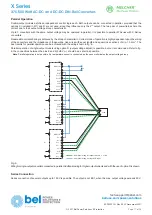
This function allows in a battery charger application for checking, whether the output is correctly following the external control
signal at the R-input (coming for instance from the temperature sensor). The logic is shown in table 19.
The open-collector output Sys-OK is protected by a Zener diode and withstands up to 58.6 V. When the system status is OK, the
signal output is low:
V
Sys-OK
< 1.5 V,
I
Sys-OK
< 50 mA.
Table
20
:
System OK (M1 with external battery sensor)
System Status
Input
V
control
sensor signal
V
Bat
theoretical
V
Bat
measured
Sys-OK
Output
System OK
OK
2.7 V
27 V
27 V
Low ohmic
Battery overcharged / temp. sensor defect / control voltage to high
OK
2.7 V
27 V
28 V
High ohmic
Overload, converter cannot follow the control signal
OK
2.7 V
27 V
24 V
High ohmic
Output does not follow control signal, since battery would be overcharged
OK
3.0 V
30 V
27 V
High ohmic
System OK
OK
2.5 V
25 V
25 V
Low ohmic
R: Adjustment of
V
o
or
V
o2
The R input allows external adjustment of the output voltage in the range of 50% to 110%
V
o nom
. Double-output models allow only
adjustment of output 2 (connected to the terminals 6, 7, 8, and 9). This enables asymmetric output voltage configuration.
Adjustment can be achieved via a resistor or an external voltage source (in the range of 1.25 – 2.75 V).
Note
: If the R input is not connected:
V
o
or
V
o2
≈
V
o nom
.
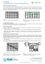
a) Adjustment by an external resistor:
Resistor
R
ext1
, connected between R (pin 2) and GND1 (pin 1) of the D-SUB connector or according to fig. 20.
V
o
V
o
= 50 –
100%
V
o nom
. R
ext1
≈
4 k
Ω
• __________
V
o nom
–
V
o
Resistor
R
ext2
, connected between R (pin 2) and VCC (pin 3) of the D-SUB connector or according to fig. 17.
V
o
– 2.5 V
V
o
= 100 –
110%
V
o nom
. R
ext2
≈
4 k
Ω
• _________________
2.5 V•(
V
o
/
V
o nom
–1)
Note:
If the R function is not included in M1 or M2, refer to figure 20 how to connect
R
ext1
or
R
ext2
.
b) Adjustment by an external control voltage
V
ext
(1.25 – 2.75 V), connected between R (pin 2) and GND (pin 1) of the D-SUB
connector or according to fig. 20.
V
o
V
ext
V
ext
≈
2.5 V • _____
V
o
≈
V
o nom
• _____
V
o nom
2.5 V
Caution:
To prevent damage,
V
ext
should not exceed 3 V, nor be negative.
Note:
If longer wires are used to connect the R input at the D-SUB connector, the wiring to pin 1 (GND1) should be done as a star point
connection. If wired differently, the output voltage setting may be adversely affected.
In battery charging systems, an external battery temperature sensor (see
Accessories
) can be connected to optimize
V
o
. However,
adjustment using the R input (pin 2 of D-SUB) is possible as well. The above shown formulas are valid, but
V
o nom
stands for the
voltage with open R input (
= V
o safe
).
F: Built-in Second Fuse
A built-in second fuse in the neutral line provides safe phase-to-phase connection at low mains voltages
(e.g. USA 120 /208 V /60 Hz systems).
The built-in second fuse also enables safe connection to the mains, where phase and neutral are not defined or cannot be identified,
as e.g. in the case of plug and socket connection to the mains via German Schuko-plugs; see also
Safety and Installation Instructions
.
Option F limits the DC input voltage to
≤
250 V.