


belfuse.com/power-solutions
BCD20021-G Rev AF, 29 November 2021
Page 17 of 26
X Series
375, 500 Watt AC-DC and DC-DC DIN-Rail Converters
© 2021 Bel Power Solutions & Protection
Safety and Installation Instructions
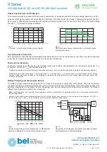
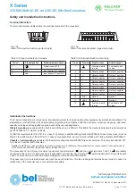
Terminal Allocation
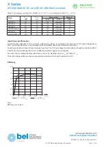
The terminal allocation tables define the electrical potential of the converters.
1
3
2
10066
1
3
5
7
9
10086
2
4
6
8
10
12
11
Fig. 14a
View of the input terminals (cage clamp style)
Fig. 14b
View of the output terminals (cage clamp style)
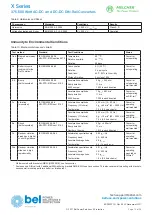
Table 13a: Input terminals of LX models
Table 13b: Terminal allocation output side
Pin no.
Pin designation
Electrical determination
1
Protective earth PE
2
N
~
Input neutral, DC negative
3
L
~
Input phase, DC positive
Pin no.
Pin des.
Single output
Double output
1
Functional earth
to load
Functional earth
to load
2
+
Output positive
Output 1 positive
3
+
Output positive
Output 1 positive
4
–
Output negative
Output 1 negative
5
–
Output negative
Output 1 negative
6
+
Output positive
Output 2 positive
7
+
Output positive
Output 2 positive
8
–
Output negative
Output 2 negative
9
–
Output negative
Output 2 negative
10
AUX1
Option 1
Option 1
11
AUX2
Option 2
Option 2
12
Functional earth
to load
Functional earth
to load
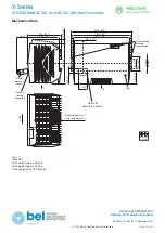
Installation Instructions
The X Series converters are components, intended exclusively for inclusion within other equipment by professional installers. The
installation must strictly follow the national safety regulations in compliance with the enclosure, mounting, creepage, clearance,
casualty, markings and segregation requirements of the end-use application.
DIN-rail mounting
is possible with the built-in snap-fit device on a DIN-rail. This fulfills the mechanical transport re quirements as
per ETSI 300019-1-2, class 2 (vertical).
To fulfill the requirements of IEC 721-3-2, class 2.1 (vertical), 2 additional fixing brackets HZZ00624-G (see
Accessories)
must be
fitted on the bottom side of the DIN-rail. For heavy duty applications, we recommend installing all 4 fixing brackets HZZ00624-G.
Chassis
or
wall mounting
is possible with the wall-mounting brackets HZZ00618 (see
Accessories)
. This complies with IEC 721-
3-2, class 2.2 (vertical and horizontal).
Caution
: Install the converters vertically, and make sure that there is sufficient airflow available for convection cooling. The minimum space
to the next device should be: top/bottom: 30 mm, left/right: 20 mm.
The converters of the X Series are class I equipment: Input terminal 1 ( ) and the output terminals 1 and 12 ( ) are reliably
connected to the case. For safety reasons it is essential to connect the input terminal 1 ( ) with protective earth. Output terminals
1 and 12 can be used to connect the output voltage(s) or the load to functional earth.
The phase input (L) is internally fused; see
Input Fuse and Protection
. This fuse is de signed to break an overcurrent in case of a
malfunction of the converter and is not customer-accessible.