


TO REMOVE MAIN PRINTED CIRCUIT BOARDS (CPU AND ADAREF)
Proceed as follows:-
1)
Remove cover screws (19) and cover
2)
Remove rear panel screws (9). 2 on each end and 5 on underside.
3)
Remove the 3 centre plate/heatsink screws from the underside.
4)
Gently ease the rear panel away from the main printed circuit boards,
disconnecting the 3 header plugs.
5)
Remove all ÔCPUÕ and ÔADAREFÕ printed circuit fixing screws (10).
6)
Remove the 2 power supply connectors PL1 and PL3 and CPU keyboard and
LCD connectors PL4 and PL5
7)
Lift out of the chassis - CPU + centre plate.
8)
To separate the ÔADAREFÕ and ÔCPUÕ printed circuit boards - cut the cable tie
holding the ADAREF power cable on the underside of the ÔCPUÕ printed circuit board and
pull ADAREF board away from CPU board disconnecting PLI/SKI and PL2/SK2.
9)
To re-assemble follow the above in reverse order firstly pushing the CPU and
ADAREF boards together and fitting a cable tie holding the ADAREF power cable in
position.
NOTE: Care should be taken not to trap the ADAREF power cable under the centre plate
when re-fitting to chassis. (Locate in cutout provided in centre plate).
* After board changes it may be necessary to reset the CPU Board to obtain correct
operation (this will reset parameters to factory set values). Power-on and while the ÒlogonÓ
information is displayed, i.e. Model No etc. Press the set key. The unit will then reset to
default settings.
28
Summary of Contents for 6110
Page 7: ...DIAGRAM 1 SET UP MENUS 7 ...
Page 8: ...DIAGRAM 2 SET UP MENUS 8 ...
Page 17: ...DETAIL OF SWITCHES ON FRONT DEFAULT LCD REAR PANEL VIEW 17 Figure 2 Figure 3 Figure 4 ...
Page 19: ...REAR PANEL LAYOUT 19 ...
Page 20: ...BLOCK DIAGRAM 20 ...
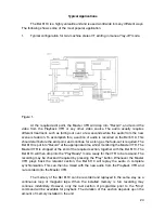
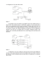
Page 22: ...BEL 6110 Lay off recorder Application Notes 22 ...