


CONNECTIONS
The rear panel has twelve connectors, a voltage selector and a combined IEC power
inlet switch and fuseholder. From left to right these are:-
Switch, Fuse, IEC 3 pin power inlet (combined EMI filter unit)
Mains power voltage selector (115V / 230V)
RS422 Serial Port 9-pin female miniature D-type (lockable)
Remote Control 9-pin female miniature D-type (lockable)
Time-Code Input 3-pin XLR type connector (female) for SMPTE input Balanced
Digital Ref: Word 50½ BNC (4k7½)
Digital Ref: Video 75½ BNC medium impedance (75½ termination link internal)
Digital Output (AES/EBU) male XLR 3-pin (110½)
Digital Input (AES/EBU) female XLR 3-pin (110½)
Digital Ref: AES (48kHz) female XLR 3-pin (110½)
Left and Right Audio Outputs 3-pin XLR type connector (male). Balanced Pin 2 hot.
Left and Right Audio Inputs 3-pin XLR type connectors (female). Balanced Pin 2 hot.
EMC COMPLIANCE
The BEL 6110 was designed and tested to comply with the EMC directive numbers
EN55103, EN55022, EN55082-1 and EN60950 when used as directed.
This unit must be used with an earthed mains lead to comply with the CE low voltage
directive.
CE
12
Summary of Contents for 6110
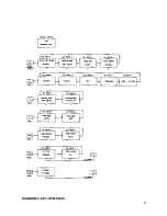
Page 7: ...DIAGRAM 1 SET UP MENUS 7 ...
Page 8: ...DIAGRAM 2 SET UP MENUS 8 ...
Page 17: ...DETAIL OF SWITCHES ON FRONT DEFAULT LCD REAR PANEL VIEW 17 Figure 2 Figure 3 Figure 4 ...
Page 19: ...REAR PANEL LAYOUT 19 ...
Page 20: ...BLOCK DIAGRAM 20 ...
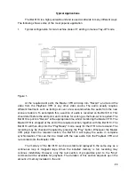
Page 22: ...BEL 6110 Lay off recorder Application Notes 22 ...