


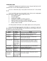


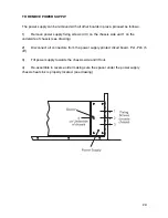

TROUBLESHOOTING
The Bel 6110 is designed and constructed to ensure a long and fault free life, but if
a problem does occur the following guidelines are provided.
The unit is constructed using 2 main printed circuit boards and 7 sub assembly
boards.
The 2 main PCBÕs carry the processor/DSP circuits (CPU) and the analog/digital
input output systems (ADAREF). Seven smaller PCBÕs carry:-
1.
The keyboard interface
2.
The LCD interface
3.
A system power supply
4.
ÔAnalogÕ I/O - Protection and EMC suppression
5.
Digital AES/EBU I/O protection and EMC suppression
6.
Time-code, remote and RS422 protection and EMC suppression
7.
Memory module or modules
All of these printed circuit boards can be rapidly replaced. (see servicing section)
If the outline fault finding suggestions which follow are unsuccessful, contact your
BEL distributor, or the main BEL distributor, who will advise you and arrange for the unit to
be repaired or provide replacement PCBÕs.
Fault
Causes
Action
ÔDeadÕ unit
Power supply
Check fuses in the IEC and supply connector then
fault PCB
check fuses & connectors on the power supply
Only fan or
Power supply
Check fuses on the power supply PCB
backlight on
fault
No record
In follow mode
Check if in follow mode there is valid timecode at
with no
timecode input on rear panel
timecode input
No audio output
No recording
Check audio is present at the inputs (PPI indicators)
made no audio
ensure the required input mode digital or analog is
at inputs digital
selected. Check input sensitivity control (front panel)
input selected
with no input
(AES)
Noisy digital
No digital REF-
Ensure that an AES reference is connected (48kHz)
AES selected
to the unit if AES REF is selected
Distorted output
Headroom
Adjust input sensitivity control
Noisy output
Loose or
Check all memory modules are fitted correctly
analog or digital
misaligned
memory module
Remote control
Remote connect-
Check remote connection is fully pushed in and lock.
inoperative or
ion not fully push-
Check cable for damage.
intermittent
ed in on rear panel
broken wires in
remote cable
21
Summary of Contents for 6110
Page 7: ...DIAGRAM 1 SET UP MENUS 7 ...
Page 8: ...DIAGRAM 2 SET UP MENUS 8 ...
Page 17: ...DETAIL OF SWITCHES ON FRONT DEFAULT LCD REAR PANEL VIEW 17 Figure 2 Figure 3 Figure 4 ...
Page 19: ...REAR PANEL LAYOUT 19 ...
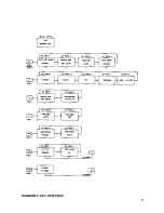
Page 20: ...BLOCK DIAGRAM 20 ...
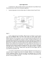
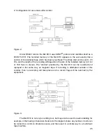
Page 22: ...BEL 6110 Lay off recorder Application Notes 22 ...