37
Heatless Desiccant Dryers
|
Instruction Manual
Section 7:
Energy Management
Alarm
Remote fault alarm: -
A remote alarm relay is built into the controller. This facilitates
the activation of a remote audible or visual indicator. The
alarm can be set to activate at the service interval and/or after
a pre-defined number of electrical faults.
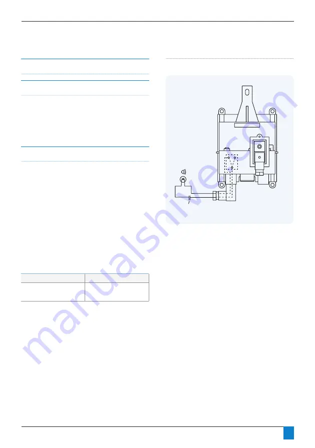
Alarm connection details
To enable the alarm facility it is recommended that a suitable
cable is brought into the controller via the rear panel with a
grommet. An external power source is required.
1. Connect the switching pole of an externally powered alarm
device to terminals 1 and 2 of alarm DIN connector.
2. With the power removed from the dryer and the alarm
lead wired as described in 1 above, remove the cover from the
DIN connection marked ‘Alarm’ and connect the wired DIN
connector ensuring the seal and screw are fitted.
External
Power Source
External
Power Source
Figure 7.8: Remote alarm wiring diagram
Alarm relay rating
Alarm connection type
3 Amp Max 28 VDC
Hirschmann GDS 207
industrial standard DIN
connector or equivalent


