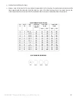
CLEARPOINT® Flanged L100-L304_us_en_2014-6 (rev. A)
7
The nominal diameter of the pipes should be as uniform as possible in order to avoid creating additional flow resistance.
Reduced pipe sections should only be installed where required for partial-flow outlets (ring, connecting or supply lines).
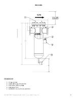
TECHNICAL SPECIFICATIONS OVERVIEW
Model
Pipe Size
ANSI
Flange
Flow
Rate
*)scfm
A
In
B
In
C1
In
C2
In
D
In
Volume
Gallons
Weight
Lbs.
Filter
element
**)
L100
4” FLG
1900
20.25
6.875
76.20
59.50
13.00
10.00
195
88(Typ)2 x
L102
4” FLG
2800
20.25
7.125
60.50
47.50
13.00
16.00
266
88(Typ)3 x
L150
6” FLG
3800
23.50
8.00
60.00
47.00
13.00
17.00
328
88(Typ)4 x
L156
6” FLG
6500
23.75
8.25
64.30
50.00
14.30
26.00
360
88(Typ)7 x
L200
8” FLG
7500
28.00
9.50
67.30
53.00
14.30
32.00
469
88(Typ)8 x
L204
8” FLG
9300
27.95
9.65
67.60
53.30
14.30
44.11
575
88(Typ)10 x
L254
10” FLG
13000
34.65
8.50
69.06
54.76
14.30
70.00
761
88(Typ)14 x
L304
12” FLG
21000
38.95
11.02
74.69
60.39
14.30
107.50
1135
88(Typ)22 x
*)
Volumetric flow at 100 psi operating pressure, related to 68°F (20 °C) and 14.5 psi absolute(1.0 bar).
Validated in accordance with ISO 12500-1, INLET CONCERTRATION 5-15mg/m3
**)
When ordering, please state the required quantity of filter elements and the degree of filtration (type).
***)
Coalescing filter = Residual aerosol content
Activated carbon filter = residual vapor content
Type
Description
Solid Particles
µm
Residual Oil Content
mg/m3 ***)
C
Coarse filter
25
1010
G
General purpose filter
5
5
G
Fine filter
0.1
1
S
Super fine filter
0.01
0.01
A
Activated carbon filter
-
0.003
R (typ)
Dust filter
Type
Type
CORRECTION FACTORS
Operating Pressure
Inlet air pressure psig 20 40 60 80 90 100 120 130 140 160 180 200
Factor
P
1
0.30 .48 .65 .82 .91 1.00 1.17 1.26 1.35 1.52 1.70 1.87
•
For the maxium volume flow, multiply the model volume flow shown in the table by the correction factor
corresponding to the working pressure.


