background image


CLEARPOINT® Flanged L100-L304_us_en_2014-6 (rev. A)                                                                                            


INSTALLATION SITE 


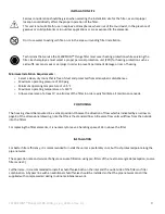
Serious consideration should be given when selecting the installation site for the filter, as an improper 
location could directly affect the proper operation of the filter. 
This unit is not suitable for use in explosive atmospheres, where risk of fire could exist, in the presence of 
gaseous or solid pollutants or in outdoor applications or areas exposed to the elements.


Don’t use water to extinguish fire on or in the 

area surrounding filter installation.


Technicians that service the CLEARPOINT® Flange filter must wear hearing protection while servicing the 
filter. Each employee must select a proper personal protection unit (PPD) for hearing protection such as 
earmuffs, ear canal caps or earplugs in order to prevent permanent damage or loss of hearing


Minimum Installation Requirements: 


Select a clean, dry room that is free of dust and protected from atmospheric disturbances. 


Maximum operating pressure of 200 psig 


Minimum operating temperature of +35 °F 


Maximum operating temperature of +140 °F 


Allow a 

clearance of at least 3’ on all sides of the 

filter in order easily facilitate all maintenance needs. 


POSITIONING 


The housing should be mounted in a vertical position. Observe the direction of flow which is indicated by an arrow on 
page 8 of the dimensional drawing, note that this is the standard flow. All reverse flow units will flow from the outside 
into the filters.  
 
For replacing the filter elements, it is necessary to leave a handling space of 34 in above the filter.  


INSTALLATION 


For better filter efficiency, it is recommended to install the unit at a preferably cool, but frost-protected point along the 
pipe network. 
 
The separation rate and service life figures assume filtration using pre-filters of the next coarser grade (exception; coarse 
filter series C). 
 
Furthermore, it is recommended to install a shutoff valve both on the inlet and the outlet side of the filters or filter 
combination. A bypass line with an additional shutoff valve should be installed so that the pipe network can still be 
supplied with compressed air during routine maintenance work.  


Summary of Contents for CLEARPOINT Series

Page 1: ...EN Operating Manual Filter with Flanged Connections CLEARPOINT Flange Filter Series models L100 to L304 READ MANUAL FIRST BEFORE INSTALLATION AND OPERATION ...

Page 2: ...EFFICIENCY OF FILTERS 6 TECHNICAL SPECIFICATIONS OVERVIEW 7 CORRECTION FACTORS 7 DIMENSIONS 8 INSTALLATION SITE 9 POSITIONING 9 INSTALLATION 9 CHECKS AND MAINTENANCE 10 FILTER ELEMENT REPLACEMENT 11 BOLT TORQUE TABLE FT LBS 12 BOLT MARKING REFERENCE 12 BOLT PATTERN REFERENCE 13 BOLT PATTERN REFERENCE con t 13 ACCESSORIES 14 SPARE PARTS 15 For technical product support please call 1 800 235 6797 an...

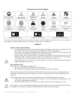
Page 3: ...or maintain filter assembly In most countries states cities and or local municipalities the installation may only be carried out by a licensed installation company Inspections must be carried out by a qualified and licensed third party firm in accordance with all applicable laws rules and regulations for the region where the filter is installed The pressure vessels used in this unit are built acco...

Page 4: ...remises must have read and understood these instructions for installation and operation The instructions should be permanently available at the place of installation CLEARPOINT filters are built according to the state of the art and the approved safety rules of engineering practice However the use of the product can endanger the health and life of attending personnel or third parties and can have ...

Page 5: ...l government SAFETY RULES The personnel carrying out the installation commissioning maintenance or repair of the unit must be properly qualified for this type of work In particular the persons concerned should Be trained and familiar with handling compressed air systems and be informed about the associated dangers For CLEARPOINT filters equipped with a BEKOMAT drain the BEKOMAT operating manual mu...

Page 6: ...ered out liquid particles gather in the lower part of the filter housing from where they are discharged either manually or automatically With coalescence filters the direction of flow through the filter elements is from the inside to the outside with dust filters the flow moves from outside to inside Activated carbon filter A The flow through the activated carbon bed proceeds from the inside to ou...

Page 7: ... L254 10 FLG 13000 34 65 8 50 69 06 54 76 14 30 70 00 761 88 Typ 14 x L304 12 FLG 21000 38 95 11 02 74 69 60 39 14 30 107 50 1135 88 Typ 22 x Volumetric flow at 100 psi operating pressure related to 68 F 20 C and 14 5 psi absolute 1 0 bar Validated in accordance with ISO 12500 1 INLET CONCERTRATION 5 15mg m3 When ordering please state the required quantity of filter elements and the degree of filt...

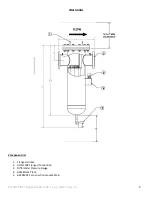
Page 8: ...ARPOINT Flanged L100 L304_us_en_2014 6 rev A 8 DIMENSIONS Component list 1 Flange Handles 2 ANSI 150 Flanged Connection 3 Differential Pressure Gauge 4 ASME Data Plate 5 BEKOMAT Zero Loss Concensate Drain ...

Page 9: ...pressure of 200 psig Minimum operating temperature of 35 F Maximum operating temperature of 140 F Allow a clearance of at least 3 on all sides of the filter in order easily facilitate all maintenance needs POSITIONING The housing should be mounted in a vertical position Observe the direction of flow which is indicated by an arrow on page 8 of the dimensional drawing note that this is the standard ...

Page 10: ...For an emergency a possibility for the shut off of the plant section must be provided Daily Carry out a general visual inspection External damage and defects Visually check for any leaks Check differential pressure gauge Pressure drop increases as element loads with solid particles Replace when pressure reaches 10 psi or you see the indicator in the red Test drain function Monthly External damage ...

Page 11: ... into the housing Retighten the nuts in order to secure the tie rod unit Replace flange gasket on top When reassembling the lid to the vessel confirm the bolt flat washer lock washer and nut are assembled in this order The lock washer will always be on the vessel side of the assembly Lubricated bolt threads in area of nut engagement Install all bolts and nuts finger tight After you have installed ...

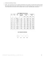
Page 12: ...drain to ensure an adequate stock of spare parts BOLT TORQUE TABLE FT LBS PIPE SIZE BOLT QTY BOLT SIZE 307A Grade A for 150 psig only Grade 5 150 FLANGE Grade 5 300 FLANGE MIN STD MIN STD 4 8 5 8 11 60 63 120 94 200 5 8 3 4 10 100 88 200 117 200 6 8 3 4 10 100 111 200 99 200 8 8 3 4 10 100 150 200 160 320 10 12 7 8 9 160 141 320 185 490 12 12 7 8 9 160 187 320 269 710 14 12 1 8 245 238 490 234 652...

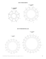
Page 13: ...CLEARPOINT Flanged L100 L304_us_en_2014 6 rev A 13 BOLT PATTERN REFERENCE BOLT PATTERN REFERENCE con t ...

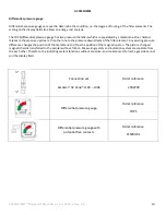
Page 14: ...the pressure downstream of the filter element Any existing pressure difference changes the position of the membrane and thus the position of the magnetic piston The pistons changed magnetic field is transferred to the pointer without friction Measuring system and indication system are separate from the each other Therefore the indicating system functions without pressure and contaminants form the ...

Page 15: ...88G 88F 88S 88A 2 4032958 4023573 4025091 L102 88C 88G 88F 88S 88A 3 4032959 4023573 4025091 L150 88C 88G 88F 88S 88A 4 4032959 4023573 4025091 L156 88C 88G 88F 88S 88A 7 4032960 4023573 4025091 L200 88C 88G 88F 88S 88A 8 4032961 4023573 4025091 L204 88C 88G 88F 88S 88A 10 4032962 4023573 4025091 L254 88C 88G 88F 88S 88A 14 4032963 4023573 4025091 L304 88C 88G 88F 88S 88A 22 4032964 4023573 402509...

Page 16: ...CLEARPOINT Flanged L100 L304_us_en_2014 6 rev A For technical product support please call 1 800 235 6797 and select Option 2 ...

Reviews: