6
Considering the example shown in Fig 2, the sum
of the maximum voltage drop introduced by each
component in the loop must be less than the
minimum power supply voltage.
Min operating voltage of 2-wire flowmeter
10.0
Maximum voltage drop caused by controller
5.0
Maximum voltage drop caused by BA354ND
1.1
Maximum voltage drop caused by cables
0.4
_____
16.5V
At 20mA the power supply must therefore have an
output greater than 16.5V
4.2 Remote indication
The BA354ND rate totaliser may be driven from
any 4/20mA signal to provide a remote indication
of rate and total flow in a Zone 2 hazardous area.
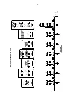
Fig 3A shows a typical application in which the
4/20mA output from a powered flowmeter drives a
BA354ND. Again it is necessary to ensure that the
4/20mA loop complies with the two design
requirements listed in section 4.1 If suitably
certified, the flowmeter may also be located in
Zone 2 as shown in Fig 3B.
Both examples show an external reset switch.
Alternatively the BA354ND may be programmed
so that the total display can be reset from the
internal push-buttons – see section 4.3.
Fig 3A
Remote indication from flowmeter in
safe area
Fig 3B
Remote indication from flowmeter in
Zone 2
4.3 Resetting the total display to zero
The BA354ND may be programmed to reset the
total display to zero when the
Up
and
Down
buttons are pushed simultaneously for 2 seconds.
If the application requires the total display to be
reset via a key-switch or from a remote location,
this can be achieved by connecting an external
switch to terminals RS1 and RS2. This switch may
be located in Zone 2 or in the safe area providing it
and the associated wiring can withstand a 500V
rms insulation test, to frame or earth. Most
industrial push-buttons and key-switches comply
with this requirement.


