3
1. DESCRIPTION
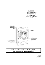
The BA324ND is a 4½ digit Ex nL certified loop
powered digital indicator which displays the current
flowing in a 4/20mA loop in engineering units. The
indicator only introduces a 1.1V drop which allows
it to be installed into almost any 4/20mA current
loop. No additional power supply or battery is
required. Housed in a robust IP66 glass reinforced
polyester (GRP) enclosure with an armoured glass
window the BA324ND is suitable for installation in
most industrial environments
The BA324ND is a third generation instrument
which, although having additional features
including a separate terminal enclosure and ATEX
certification, remains functionally compatible with
the original BA324N and BA324NC.
The main application of the BA324ND is to display
a measured variable or control signal in a Zone 2
hazardous area. The zero and span of the display
are independently adjustable so that the indicator
can be calibrated to display any variable
represented by the 4/20mA current, e.g.
temperature, flow, pressure or level.
The BA324ND has been issued with a Certificate
of Conformity to BS EN50021:1999, Type of
protection 'nL' by ITS Testing and Certification Ltd.
In addition, the BA324ND complies with the
European ATEX Directive 94/9/EC for Group II,
Category 3G equipment.
2. OPERATION
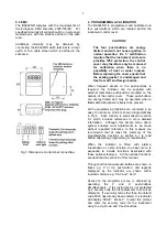
Fig 1 shows a simplified block diagram of a
BA324ND. The 4/20mA input current flows
through resistor R1 and forward biased diode D1.
The voltage developed across D1, which is
relatively constant, is multiplied by a switch mode
power supply and used to power the instrument.
The voltage developed across R1, which is
proportional to the 4/20mA input current, provides
the input signal for the analogue to digital
converter.
Each time a 4/20mA current is applied to the
instrument, initialisation is performed. After a short
delay the following display sequence occurs:
-1.8.8.8.8
Display test in which all
segments of the display
are activated for 0.5
seconds.
Blank display
For 0.5 seconds.
Decimal points For 3 seconds.
cycled
Input current
Using calibration
display in
information stored in
engineering
instrument memory.
units.
Fig 1 Simplified block diagram of BA324ND
2.1 Controls
The BA324ND is controlled and calibrated via four
push-button switches which are located behind the
instrument control cover, or as an option on the
instrument cover. In the display mode i.e. when
displaying a variable, these switches have the
following functions:
P
While this button is pushed the
indicator will display the input current
in mA, or as a percentage of the
instrument span depending upon how
the indicator has been programmed.
When the button is released the
normal display in engineering units
will return. The function of this push-
button is modified when alarms or a
tare function are fitted to the indicator.
Down
While this button is pushed the
indicator will display the number
which the indicator has been
calibrated to display with a 4mA input.
When released the normal display in
engineering units will return.

