background image

9.

Laser markings

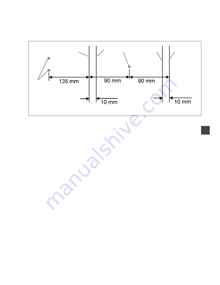
According to the equipment the 100-68 is provided with 6 lasers for
marking the positioning points.

The following values are basic values:

1 : Needles

2 : Marking of the front positioning point

3 : Auxiliary positioning line for the production of men’s jackets

4 : Marking of the central positioning point

5 : Auxiliary positioning line for the production of men’s jackets

6 : Marking of the rear positioning point

3

39

1

2

3

4

5

6

Summary of Contents for 100/68

Page 1: ...al Piped Pocket Sewing unit Operating instructions Assembly instructions Service instructions Programming instructions 1 2 3 Ausgabe Edition 11 2007 Printed in Federal Republic of Germany Teile Nr Part No DOC000045 4 ...

Page 2: ......

Page 3: ...fabric waste Service maintenance inspection repair and or Transport The user also has to assure that only authorized personnel work on the machine The user is obliged to check the machine at least once per shift for apparent damages and to immediatly report any changes including the performance in service which impair the safety The user company must ensure that the machine is only operated in per...

Page 4: ...on and special maintenance work must only be carried out by technicians or persons with appropriate training 7 For service or repair work on pneumatic systems disconnect the machine from the compressed air supply system max 7 10 bar Before disconnecting reduce the pressure of the maintenance unit Exceptions to this are only adjustments and functions checks made by appropriately trained technicians...

Page 5: ...2 2 7 1 Swivelling the corner knife station in and out 12 3 Switching on Starting the sewing process Program stop Switching off 14 3 1 Switching on 14 3 2 Reference position 15 3 3 Starting the sewing process 15 3 4 Program stop 16 3 5 Switching off 16 4 Working methods 17 4 1 Working method Production of trousers 18 4 2 Working method Breast welt pocket 20 5 Quick clamp adjustment and folder moni...

Page 6: ...2 ...

Page 7: ...emi skilled operating personnel will be working on our products so that all usual operations and where applicable their risks are presumed to be known 1 2 Brief description The Beisler 100 68 is a sewing unit for automated runstitching of piped pocket flap pocket and welt pocket openings with rectangular or slanted pocket corners The slanted pocket corners result from the offset of the two seam ro...

Page 8: ... microcomputer does the control tasks supervises the sewing process and indicates operating errors and malfunctions in the display Optional equipment Due to a flexible system of optional equipment the sewing unit can be optimally adapted to the respective application at low cost Sewing equipment and folders Please see parts list of cl 100 68 for details concerning sewing equipment and folders for ...

Page 9: ...e right Swivel the entire folding station 1 with folder to the right The sewing point is freely accessible Note When the sewing unit is switched on a safety message is indicated in the display of the control panel Folding station swivelled out Swivelling the folding station back Swivel the folding station 1 back ATTENTION After having been swivelled back the folding station must snap in catch 2 1 ...

Page 10: ...sheet only with the sewing unit switched off Switch the main switch off For changing the hook thread bobbins Lift the fabric sliding sheet 2 at with the pin 1 and swivel it to the left For complete removing for maintenance work and adjustments Lift the fabric sliding sheet at the hind pin 3c completely 6 2 1 3 1 3 ...

Page 11: ...bel no 120 on the thread reel of a core thread corresponds e g to the thread size Nm 80 2 see table values in brackets In case of monofilament threads you can use needle threads and hook threads of the same thickness The best results are achieved with soft and elastic threads software of the thread thickness 130 Denier Recommended thread thicknesses Needle size Core thread Core thread Nm Needle th...

Page 12: ...essible Loosen screw 2 and remove needle from needle holder 1 Push a new needle into the drill hole of needle holder 1 as far as it will go ATTENTION Seen from the operator s side of the sewing unit the hollow groove 4 of the left needle must point to the left and the hollow groove 5 of the right neele to the right see sketch Tighten screw 2 ATTENTION After the changeover to another needle size th...

Page 13: ... 4 Threading the needle thread Caution Risk of injury Switch the main switch off Thread the needle threads only with the sewing unit switched off See the illustration for threading the needle threads 1 9 ...

Page 14: ...al supply groove of the bobbin hub in clockwise direction The full supply groove guarantees a secure winding start even in case of monofilament threads With the thread supply in the supply groove it is ensured that the pocket opening can be safely finished after the remaining thread monitor has produced the message bobbin empty The reflecting surface 4 of the bobbin hub has to be kept clean Press ...

Page 15: ... indicates the message shown in the right picture The remaining thread in the supply groove of the bobbin hub guarantees that the pocket opening is safely finished The transport carriage stops in its rear end position Caution Risk of injury Switch the main switch off Clean the lenses of the light barriers only with the sewing unit switched off Switch the main switch off When changing the bobbin al...

Page 16: ...wo step motors is freely selectable for the seam beginning and the seam end and amounts to max 10 mm in relation to the second seam The lateral distance of the corner knives to the seam is manually adjustable The whole unit can be folded out for adjusting and servicing 2 7 1 Swivelling the corner knife station in and out The corner knife station 1 can be swivelled out completely Caution Risk of in...

Page 17: ...r the sewing unit Pull catch 2 down Swivel the corner knife station 1 in completely Release catch 2 ATTENTION Risk of breakage The holder 2 must snap in audibly Note If the corner knife station is swivelled out with the sewing unit switched on the following message appears 1 13 1 2 1 ...

Page 18: ...main switch 1 on turn in clockwise direction The control loads the machine program The start screen appears in the display of the control panel and indicates the following message Press the program stop switch 2 If the transport clamps are not at the reference position a reference run is made 14 2 1 ...

Page 19: ...its rear end position The display changes over to the main screen of the sewing unit 3 3 Starting the sewing process Actuate the central foot switch By actuating the central foot switch repeatedly the different steps of the feeding process are started one after the other The individual steps depend on the working method and on the equipment of the sewing unit For feeding corrections Actuate the ri...

Page 20: ... in case of operating errors needle breakage material accumulation etc the safety system of the 100 68 will react as follows Press program stop 1 The sewing process is stopped immediately 3 5 Switching off Switch the main switch 2 off turn counter clockwise 16 1 2 ...

Page 21: ...adjust and align the positioning aids e g positioning marks marking lamps guides etc Feeding and starting the sewing process Here you will find a list of the individual feeding steps with practice oriented examples ATTENTION The steps of the feeding process are dependent on the equipment of the respective sewing unit So the feeding steps described in the examples apply to sewing units with the sam...

Page 22: ... markings 2nd step Position the hind trousers at the central positioning point 5 and the marking 4 Actuate the central foot switch The hind trousers is clamped by the fabric downholder 3 Smooth out the clamped hind trousers in the dart area If the machine is additionally equipped with vacuum Actuate the left foot switch The vacuum is switched on 3rd step Actuate the central pedal The transport cla...

Page 23: ...1 19 3 4 5 6 7 8 2 1 ...

Page 24: ...as laser Step on the start pedal The vacuum is switched on The jacket front is sucked 2nd step Remove breast welt 1 Position pocket bag 4 at the left laser Step on the central pedal The fabric clamps move to the front The right clamp 6 clamps the jacket front The left clamp 7 remains pressureless 3rd step Position breast welt 8 at the stop of the left fabric clamp at the front laser Fold back seam...

Page 25: ...21 1 5 9 8 7 6 2 3 1 10 4 ...

Page 26: ... the solenoid switches SC103 and SC106 According to the equipment the magnets are fitted on the folders in different positions Depending on the selected folder the clamps are adjusted automatically 1 Folder for double piping 2 Folder for single piping left 3 Folder for single piping right 22 1 2 3 SC103 SC106 ...

Page 27: ... off at the seam end e g when sewing inside and outside pockets of men s jackets A sensor supervising the tape feed is integrated in the tape feeding unit The whole sequence is realized within the machine time so that there are no further feeding or secondary processing times If the tape is not pulled during the sewing process e g in case of accumulation or wrong threading a message is produced by...

Page 28: ...24 9 8 7 11 10 2 1 5 4 3 3 5 ...

Page 29: ...the sketch Swivel the fabric sliding sheet 9 back again Tap the key The reinforcement strip is cut off and moved to the initial position Function and operation Before the next sewing cycle the reinforcement strip is fed forward a little by the transport roller of the feeding device When sewing the pocket opening the reinforcement strip is seized and sewn in according to the set sewing length The t...

Page 30: ...d rod switches the zipper feed on and the drive rollers 7 and 8 go on feeding the zipper until the switch rod drops and switches the feed off again Thus it is made sure that there is always enough zipper material available for sewing Activating and switching the zipper device on Tap the key The zipper device is activated Caution Risk of injury During the swivelling and cutting process 26 ...

Page 31: ...he filter ring 6 at the vacuum valve 5 Blow out with compressed air pistol Clean and check daily Check the water level in the pressure regulator The water level must not reach the filter insert After screwing in the drain screw 2 blow the water out of the water separator 1 under pressure The filter insert separates dirt and condensed water After a certain time of operation wash the dirty filter tr...

Page 32: ... SP NK 10 SP NK 10 can be bought from the sales office of Beisler GMBH Checking the oil level in the oil reservoir 2 for the lubrication of the machine head The oil level in the oil reservoir 2 must not drop below the marking Min If necessary fill oil through the drill hole 1 up to the upper marking 28 2 1 ...

Page 33: ... 68 1 Scope of delivery 3 2 General notes 3 3 Electrical connection 4 3 1 Connecting the DACIII control panel 4 3 2 Making the mains connection 4 4 Pneumatic connection 5 5 Connection to the factory own vacuum unit 6 6 Putting into operation 7 2 ...

Page 34: ...2 ...

Page 35: ...ompressed air pistol Thread reel holder Material trays for additional parts to the right of the operator and under the table top Tools and small parts in the accessories Feeding devices and sewing equipment according to the working method Optional equipment 2 General notes ATTENTION The sewing unit must only be installed by trained specialist staff Any work on the electrical equipment of the sewin...

Page 36: ...icians or correspondingly instructed persons The mains plug must be pulled out 3 1 Connecting the DACIII control panel Put the control panel 1 in the holder 2 and screw it tight Push the plug 3 into the control panel cautiously Secure the plug with the two screws 3 2 Making the mains connection Connect the mains plug 4 3 2 1 ...

Page 37: ...the compressed air maintenance unit Connect the connecting hose 4 to the shut off valve 3 and to the compressed air net Setting the operating pressure The operating pressure amounts to 6 bar It can be read off at the manometer 2 For setting the operating pressure pull up and turn the rotary handle 1 Turn in clockwise direction increase the pressure Turn counter clockwise reduce the pressure ATTENT...

Page 38: ... unit facilitates the precise feeding and positioning of the workpiece on the worktable 1 Connect the hose of the factory own vacuum unit to the connection 2 Note If no factory own vacuum unit is available a vacuum unit has to be ordered additionally 6 1 2 ...

Page 39: ...foot switch the different steps of the feeding process are released one after the other and the sewing process starts The individual steps depend on the working method and on the equipment of the sewing unit ATTENTION Please take care that material is positioned under the transport clamps at the sewing start Moving the transport carriage without material may damage the coating of the transport cla...

Page 40: ......

Page 41: ... 3 Distance between the transport clamps and the sole of the folder 14 3 4 Parallelism of main clamp and sliding sheet 15 3 5 Folding slides 16 3 5 1 Adjusting travel and parallelism of the folding slides 16 3 5 2 Position of the folding slide when retracted 17 3 5 3 Adapting the folding slide 18 3 6 Flap clamp 19 3 6 1 Flap clamp position 19 3 6 2 Opening stroke of the flap clamp 20 3 7 Changing ...

Page 42: ...sting the slant of the corner incisions 37 8 5 Exchanging the corner knives 38 9 Laser markings 39 10 Photocells for flap scanning 40 11 Fabric sliding sheet and vacuum plate 41 11 1 Adjusting the height of the vacuum plate 41 12 Adjusting the optional equipment 42 12 1 Downholder 42 12 2 Ejector roller 43 12 3 Zipper scissors 44 13 Hook lubrication 48 14 Locator and tooth belt disc 49 15 Maintena...

Page 43: ...ns Before any adjusting operations of parts involved in the stitch formation are made Insert a new needle without any damage Caution Risk of injury Before repair converting and maintenance work is done Switch the main switch off and disconnect the sewing unit from the pneumatic supply system Exception Adjusting operations carried out with the help of test or setting programs Adjusting operations a...

Page 44: ...tenance and repair work the machine head can be raised For this purpose the transport carriage must be in its rear position Caution Risk of injury Switch the main switch off Raise or lower the machine head only with the sewing unit switched off 4 1 2 4 3 ...

Page 45: ...nd adjusting now Caution Risk of injury Do not reach into the cutout of the table top when the machine head is raised Swinging the machine head back Hold the machine head tight Lift the machine head cautiously until catch 5 releases Lower the machine head cautiously into the cutout of the table top Swivel the fabric sliding sheet back again and let it catch Loosen the screw at the locking lever 4 ...

Page 46: ...stance of 1 mm between the limit switch 1 and the switching screw 4 When the transport carriage has gone back so far that the switching screw 4 stands centrically under the switch 1 there must be a distance of 2 mm between the transport carriage 5 and the stop 6 Caution Risk of injury Switch the main switch off Check and adjust the switch and the stop for the rear end position of the transport car...

Page 47: ...ch 1 Check the distance of 1 mm between limit switch 1 and switching screw 4 Correction Loosen the counternut 3 at the switching screw 4 Adjust the height of screw 4 Distance between switching screw and limit switch 1 mm Tighten the counternut 3 2 1 3 Stop guide for the transport carriage Checking Push the transport carriage 5 to the rear until the surface of the switching screw 4 is located centr...

Page 48: ...s front end position there must be a distance of 1 mm between the limit switch 1 and the switching screw 4 When the transport carriage has moved forward so far that the switching screw 4 stands centrically under the switch 1 there must be a distance of 2 mm between the transport carriage 7 and the stop 6 Caution Risk of injury Switch the main switch off Check and adjust the switch and the stop for...

Page 49: ...he limit switch 1 Measure the distance between the needles and the fronts of the transport clamp This must amount to 325 mm Adjust the limit switch 1 in the slotted hole accordingly 2 2 3 Stop guide for the transport carriage Checking Push the transport carriage 7 to the front until the surface of the switching screw 4 is located centrically above the limit switch 1 Check whether in this transport...

Page 50: ... high toothed belt tension Reduced durability Noisy running Consequences of a too low toothed belt tension No faultless mesh between belt teeth and disc toothing The teeth may skip over under load Non uniform stitch lengths Loss of steps possible Unscrew the screws 1 and take off the covering cap 2 Place the test load in the middle of the toothed belt e g with the help of a spring balance The tens...

Page 51: ...Correction Loosen the counternut 3 Adjust the toothed belt tension with the Allen screw 4 Tighten the counternut 3 3 11 4 3 ...

Page 52: ...losed the raised transport clamps 1 and 2 must pass the machine arm without hitting it The distance between the front edges of the raised transport clamps and the fabric sliding sheet should amount to 28 mm on the left and on the right Push the transport carriage under the machine arm Check the stroke of the two transport clamps Correction Loosen screw 4 Adjust the height of the transport clamps T...

Page 53: ...cking The transport clamps 1 and 2 should run parallel to the edge of the sliding sheet 3 Push the transport carriage to the front Check the distance of the transport clamps to the edge of the sliding sheet Correction Loosen the screws 4 and 6 Adjust the transport clamps with the screws 5 so that they are in parallel position to the edge of the sliding sheet Tighten the screws 4 and 6 3 13 3 2 1 6...

Page 54: ...s on both sides as well as an unhindered material feed Caution Risk of injury Switch the main switch off Check and adjust the transport clamps only with the sewing unit switched off Attention Risk of breakage Before adjusting the folder has to be correctly aligned see chapter 4 2 Position of the folder as to the needles and the centre knife Push the transport carriage to the front Let the compress...

Page 55: ...and checking The main clamp 1 must be in parallel position to the sliding sheet over its whole length Move the clamp to the feeding position Place thin fabric under the clamping arms Close the main clamp Pull the fabric out to the side and check for equal distance Correction Loosen the counternuts 2 Adjust the pressure with the Allen screws 3 Tighten the counternuts 2 again 3 15 1 3 2 ...

Page 56: ...e folding slides 1 and 2 have to be shifted by the following values when extending and retracting Needle distance 10 mm approx 3 5 mm Needle distance 12 mm approx 4 5 mm Needle distance more than 14 mm max stroke Check the distance of the folding slides Correction Loosen the screws 3 Adjust the cylinder 4 correspondingly Align the folding slides in parallel position Tighten the screws 3 Check dist...

Page 57: ... sewing unit switched off Standard and checking When retracted the folding slide 2 must be located 0 5 mm behind the edge of main clamp 1 Check the position of the folding slide Correction Loosen counternut 3 Adjust the screw 4 in such a way that the folding slide 2 is located 0 5 mm behind the edge of main clamp 1 Tighten the screws 4 3 17 4 3 2 1 ...

Page 58: ...g slide 1 must be guaranteed so that it can automatically adapt itself to the thickness of the material to be processed The folding slide 1 must have no axial backlash Check the folding slide 1 in the holder for lateral clearance Correction Loosen the counternut 2 Adjust the folding slide with Allen screw 3 in such a way that there is neither clearance nor rough rotation Tighten the counternut 2 1...

Page 59: ... unit switched off Standard and checking The flap clamps 2 must have a distance of 5 mm parallel to the inside of the main clamp 1 Close the flap clamp manually Check the distance between flap clamp 2 and the inside of main clamp 1 Correction Loosen the screws 4 Shift the flap clamp holder 3 correspondingly Tighten the screws 4 3 19 2 1 4 3 5 mm ...

Page 60: ...ing stroke of the flap clamp 3 must be adjusted in such a way that the whole length of the flap clamp is pressed against the main clamp when the flap clamp cylinder 2 is extended Switch the sewing unit on Close the flap clamp Check whether the flap clamp is pressed against the main clamp over its whole length Correction Loosen the screws 1 Shift the cylinder 2 correspondingly Tighten the screws 1 ...

Page 61: ... main clamps In case of material processing problems the rubber strips should be checked and replaced if required Check the rubber strips Correction Unscrew the screws 5 Take the clamp off Unscrew the screws 3 Exchange the rubber strips 4 and tighten with the screws 3 Mount the clamp again Note When processing thick fabrics it is of advantage to equip the clamp with a thicker rubber strip or to fi...

Page 62: ... unit switched off Dismounting the folder Loosen the screw 4 Pull the folder 3 to the front out of the drill holes 1 and 2 Cautiously remove the folder in downward direction Inserting the folder Insert the folder 3 in the holder with its fastening drill holes 1 and 2 on top and push it to the very back Tighten the screw 4 22 2 1 4 3 ...

Page 63: ...knife 3 penetrates the centre knife protection 2 the hind edge of the knife must be flush with the knife protection Make the machine pressureless Press the folder down completely by hand Check the position of the folder sole to the needles and to the centre knife Correction Make the machine pressureless Press the folder 2 down manually Loosen the screws 6 slightly Align the folder 2 as to the cent...

Page 64: ...de roller 4 and the lowest point of the guide groove 3 When the folder is raised When the folder is raised there must still be some clearance between the guide roller 4 and the highest point of the guide groove 3 Press the folder down to the fabric sliding sheet by hand For this purpose turn the stop 6 back if required Check the air gap between guide groove 3 and guide roller 4 Lift the folder up ...

Page 65: ...lowered the distance between the folder sole and the sliding sheet amounts to approx 1 2 mm dependent on the fabric The integrated spring presses the folder back so that the piping strip is safely seized when sewing during the last section of the backward movement the cylinder is pressureless Turn the stop screw 10 in such a way that if the folder is lowered the stop screw 10 abuts on the stop 11 ...

Page 66: ...he guide plates and the needle head as well as to thread breakage The distance between the sole top 1 and the bottom of the guide plate 2 should not exceed 0 5 mm Only when processing especially thick materials the distance has to be increased Lower the folder Check the position of the guide plates as to the needles Correction Aligning the guide plates Cautiously align the guide plates by means of...

Page 67: ...nitial bartack If the pressure is too high the flap or the additional parts are pushed back at the seam beginning If the pressure is too low the material may be lifted the stitch formation may be incorrect or the needles may break Adjusting the pressure of the guide plates Loosen the counternut 7 Adjust the pressure on the guide plate with the Allen screw 6 Tighten the counternut 7 3 27 7 6 ...

Page 68: ... clamped at the clamping piece 1 and cut off by knife 4 After the first stitches of the next seam the clamped needle threads are released By means of the springy clamping sheet 1 the thread catcher 3 abuts flat on the knife 4 Thus the knife is automatically in parallel position Function check Call up the adjustment and test program Selecting the output elements see programming instructions chapter...

Page 69: ...catcher from the machine head Unscrew the screws 6 Remove knife 5 Unscrew screw 7 and remove knife protection 8 Unscrew screw 4 on the rear Take off the needle thread catcher 3 Insert new thread catcher and tighten with screw 4 Put on new knife 5 and tighten with screws 6 Set the dimensions 2 5 3 mm and 1 5 mm Make a cutting and clamping test Adjust the clamping pressure by means of screw 10 if re...

Page 70: ...counterknife in the throat plate The center knife 2 must abut on the stationary knife in the throat plate with a slight pressure Move the centre knife 2 to the bottom dead centre Check whether the edge of knife 2 is max 1 mm under the stationary knife Correction Adjusting the height of the knife Move the centre knife to the bottom dead centre Loosen screws 1 Adjust the height of centre knife 2 Tig...

Page 71: ...position any more after the sewing process Furthermore the knife will quickly get blunt which may result in inaccurate cutting different seam lengths inexact corner incision and fullness within the seam 6 2 Needle protection The needle protection 7 is fixed on the holder of the needle thread catcher It should be located 1 mm deeper than the point of the centre knife 2 and 1 0 1 5 mm from its back ...

Page 72: ...has a distance of 27 2 mm to the edge 1 and a distance of 0 1 mm to the nose of bobbin case 4 Swivel the thread catcher out Check whether the point 2 has a distance of 27 2 mm to the edge 1 Check whether there is a distance of 0 1 mm between the thread catcher and the nose of the bobbin case 4 Correction Loosen the screws 3 Adjust the thread catcher 2 correspondingly Tighten the screws 3 Counterkn...

Page 73: ...s 1 all four corner knives are brought to a basic position at first Loosen screw 6 Turn the corner knife holder 2 in such a way that the face side 3 is in a line with the face side 4 of the knife support 5 Tighten screw 6 Adjust the other three knife holders as described Adjust the grub screw 7 in such a way that the edges of the opposite knives have a distance of 0 1 to 0 3 mm Grub screw 7 to the...

Page 74: ...es of a too high toothed belt tension Reduced durability Noisy running Consequences of a too low toothed belt tension No faultless mesh between belt teeth and disc toothing The teeth may skip over under load Non uniform corner stitches Check the belt tension with a spring balance Correction Loosen the counternut 3 Adjust the belt tension with the eccentric screw 2 Tighten the counternut 3 34 1 3 2...

Page 75: ...ched off Standard checking The corner incisions must be symmetrical to the seams Set the maximum sewing length at the control Iron a piece of interfacing on a workpiece Thus the corner incisions are better visible Make a test seam Check seam and cutting pattern Correction of the corner incision at the seam end Swivel the corner knife station 1 out completely 3 35 1 ...

Page 76: ...knife station back again Correction of the corner incision at the seam beginning Loosen the screw 5 slightly Adjust the corner knife station with the hexagon screw 4 ATTENTION Observe the position of the eccentric Setting range Tighten the screw 5 Make a test seam Check seam and cutting pattern 36 3 2 5 4 ...

Page 77: ... as close to the seam as possible approx 1 mm but must not cut it Set the maximum sewing length at the control Sew a test seam It is advisable to iron a piece of interfacing on the workpiece before Thus the corner incisions are better visible Check seam and cutting pattern Loosen screw 6 Adjust the corner knife holder 2 correspondingly Tighten screw 6 Adjust the other three knife holders according...

Page 78: ...ed off Risk of cuts Do not reach into the sharp edges of the corner knives Blunt knives are to be exchanged against a set of knives included in the accessories Swivel the corner knife station out Loosen screw 2 Remove the old corner knife Insert a new corner knife in the knife holder 3 Tighten screw 2 Swivel the corner knife station in again 38 3 2 ...

Page 79: ...The following values are basic values 1 Needles 2 Marking of the front positioning point 3 Auxiliary positioning line for the production of men s jackets 4 Marking of the central positioning point 5 Auxiliary positioning line for the production of men s jackets 6 Marking of the rear positioning point 3 39 1 2 3 4 5 6 ...

Page 80: ...e light beam of the photocells shines on the reflected foil Correction Loosen the screws at the photocell Adjust the photocell Tighten the screws at the photocell Correction of left light barrier for breast welt pocket As far as sewing units for breast welt pockets are concerned the left light barrier 4 is automatically set to the correct position by the cylinder 6 when selecting a breast welt pro...

Page 81: ...t and swivel them to the left Check the height of the vacuum plate as to the table top Caution Risk of injury Switch the main switch off Adjust the vacuum plate only with the sewing unit switched off The vacuum plate is connected with the table top support by four core pins 2 Turn the core pins 2 In clockwise direction vacuum plate higher Counter clockwise vacuum plate lower Readjust the support s...

Page 82: ...ing sheet It must be aligned in such a way that it is not hit by the opened clamps Adjusting the downholder Loosen the screws 2 at the holder 1 Adjust the height of the downholder 3 When the pedal is actuated the extended piston rod should just touch the hole in the fabric sliding sheet Align the downholder 3 to the back in machine head direction The piston rod should hold the hind trousers part c...

Page 83: ...off The transport rollers must be aligned in parallel position to the table top and the centre of the pocket opening Adjusting the height of the transport rollers In lowered position both transport rollers 1 and 2 should equally rest on the table top Loosen screw 4 Shift the operating lever 5 in such a way that both rollers rest on the table top with slight pressure Tighten screw 4 Adjusting the t...

Page 84: ...her the zipper parts are within the scissors the lower is the wear and tear of the scissors parts When swivelled in the scissors must not touch the needles Adjusting the scissors Loosen counternut 7 Press the scissors 2 down manually and adjust it with the piston rod 6 in such a way that the scissors is in parallel position to the support sheet Tighten counternut 7 Loosen screws 4 Adjust the dista...

Page 85: ...n switch off Check and adjust the carriers only with the main switch switched off Standard During the feed the two carriers 1 should rest on the zipper parts centrally and with equal pressure The buffers 5 of the carriers have to be extended by the cylinders 3 and 4 so far that the guide rail 2 is transported without slippage 45 3 1 5 4 3 2 ...

Page 86: ...46 3 2 1 5 4 7 6 8 7 10 9 ...

Page 87: ...riers The carriers are positioned correctly if there is a distance of approx 2 mm between the rotary disc 6 of the scissors and the guide rail 7 in the front end position of rail 7 Push the guide rail 7 right to the front Loosen screws 8 Adjust the guide rail in such a way that there is a distance of approx 2 mm between the rotary disc 6 of the scissors and the guide rail 7 Tighten screws 8 Carrie...

Page 88: ...ted by the manufacturer with the screws 1 and 2 It should be reduced or increased in special cases only Adjust the screws 1 and 2 Screw the screws in less oil Screw the screws out more oil Attention Do not screw in the screws too deeply The oil wick may be damaged 48 2 1 ...

Page 89: ...area 3 when the machine is positioned After positioning the thread lever should be in the top dead centre Adjusting the toothed disc Reposition the toothed belt 4 correspondingly Adjusting the positioning disc Turn the sewing machine into the position thread lever in top dead centre Loosen screws 7 Turn the cam segment 8 in such a way that the switch cam 6 stands exactly on the locator 5 Tighten s...

Page 90: ... and thread tails from the area around the hook and the throat plate X Supply the oiling points with oil see Operating Instructions chapter X Check the oil level in the oil reservoir X Check the oil flow at the inspection glass X Check the hook lubrication X Clean the lenses of the bobbin thread monitor X Clean the reflected foils X Drive unit and transport carriage Check state and tension of the ...

Page 91: ...est 35 6 6 2 1 Testing the corner knife unit 36 6 6 2 2 Testing the bobbin thread monitor 41 6 6 2 3 Testing the centre knife 42 6 6 2 4 Testing the ejector roller 43 6 6 2 5 Testing the step motor for the transport clamp 44 6 6 2 6 Testing feeding operation material feed and sewing cycle 45 6 6 2 7 Testing the sewing motor 46 6 6 3 DAC Update 48 6 6 4 Storing and loading program data with the USB...

Page 92: ...Index Page 6 6 8 2 Init global parameters 57 6 6 8 3 Init all sewing parameters 57 6 6 8 4 Init sequences 57 6 6 9 Configurating the menu level 1 58 6 9 9 1 Language selection 59 6 7 Version 59 ...

Page 93: ...ves nor inconvenient programming of offset seams is required Setting and test programs A comprehensive test and monitoring system is integrated in the DACIIIcontrol A microcomputer does the control tasks supervises the sewing process and indicates operating errors and malfunctions Errors and test results are indicated in the touch screen display When the machine is operating normally the display s...

Page 94: ...ch function parameter on off select previous next step of the value activate the test program Escape key Display the old value again OK key Open window to set the selected function parameter Take over the set value Function symbols Direct selection of function parameter 2 1 Operating the touch screen monitor To start a function touch the screen with a fingertip where the corresponding symbol is di...

Page 95: ... each function is briefly explained in an information line The individual parameters as well as the setting and test programs are arranged in various groups Switch the main switch on Actuate the reset key Main screen Sewing programs Menu level 1 Seam sequence Seam function Copy seam programs Seam parameters Global parameters Service Version 5 4 ...

Page 96: ...at the control panel The display changes over to the main screen Calling up the menu levels Switch the main switch on The control loads the machine program The start screen appears in the display of the touch screen monitor Press the program stop switch at the control panel The display changes over to the main screen Press the symbol You get to the menu level 1 6 ...

Page 97: ...s are altered in the individual parameter screens Tap the desired parameter The symbol of the selected parameter is framed in blue Tap the desired parameter once again The function is switched on off or a window with the prompt or the current values appears 4 7 ...

Page 98: ... flap pocket left part 12 Slanted piped pocket right part 13 Slanted piped pocket left part M03 20 Men s jacket inside pocket with fleece pocket length 60 mm 21 Men s jacket inside pocket with fleece pocket length 100 mm 22 Men s jacket inside pocket with fleece pocket length 150 mm 23 Men s jacket inside pocket with fleece pocket length 150 mm M04 30 Hip pocket 31 Front trousers pocket 32 Hip poc...

Page 99: ...he left half of the display shows the seam pattern of the selected seam program Storage location and seam program The top right corner of the display shows the program number and the selected pocket sequence Move the cursor to the desired seam program number Press the OK key The seam program is activated Press the OK key The seam program is deactivated NOTE If no seam program is active an error me...

Page 100: ...r on off Vacuum automatic Tape feed on off Holding stamp on off Activate deactivate left flap clamp Activate deactive right flap clamp Activate deactivate light barriers Feeding position on off Zipper scissors and zipper unwinder on off The functions and adjustments of the individual seam functions are described more exactly in the chapters 5 4 Seam parameters Further operating keys Activate deact...

Page 101: ...unter daily piece counter The current reading of the piece counter is displayed on the right under the parameter symbols The piece counter indicates the number of pieces produced after the last counter reset Cursor keys Changing between the individual icons OK key Activating or deactivating of functions Reset key Resetting of functions 11 4 ...

Page 102: ...s 6 1 Seam sequences Under this menu item it is possible to allocate seam programs to the individual storage locations A total of 20 independent storage locations is available Up to 6 seam programs can be combined on every storage location in any desired order Press the symbol on the main screen The display changes over to the screen menu level 1 Tap the symbol seam sequence The screen seam sequen...

Page 103: ...uences are displayed in red 0 seam program location is empty Tap the first storage location Example Tap a 0 for the seam program The following screen appears Enter the number 01 99 of the desired seam program Example 33 0 no seam program Tap the OK key The display returns to the main screen 13 4 ...

Page 104: ...ipment Select the icon with the cursor keys The icon is framed in blue Tap the Return key The function is activated The icon is displayed with a black background or Tap the seam function key directly The function is activated The icon is displayed with a black background NOTE It is advisable to activate only those functions with which the machine is equipped 14 ...

Page 105: ...dapt the seam parameters or seam functions of the new program to your requirements Copying the seam program ATTENTION Existing program settings are overwritten Tap copy seam programs Select new seam program location Example Program No 32 Tap source The numeric pad appears Tap the number of the source program Tap destination The numeric pad appears Tap the number of the new program location Tap the...

Page 106: ... selected pocket program is indicated in the upper part of the display e g No 32 If available the pertaining program name is displayed e g Program 32 Tap the desired parameter or select it with the cursor keys The symbol of the selected parameter is blue shadowed In the screen numeric pad the minimum and maximum value valid for the respective function is indicated With the key an input can be dele...

Page 107: ...500 2000 rpm Factory setting 1500 rpm 4 Speed within the seam Via this parameter the speed within the seam is set Input 500 3000 rpm Factory setting 2500 rpm 5 Speed at the seam end via this parameter the speed at the seam end is set Input 500 2000 rpm Factory setting 1500 rpm 6 Seam section speed at the seam beginning Via this parameter the seam section at the seam beginning to be sewn with the s...

Page 108: ...5 99 mm Factory setting 10 mm 13 Bartack length at the seam beginning Via this parameter the bartack length at the seam beginning is set If this value is set to 0 it is automatically sewn with condensed stitches Input 0 20 mm Factory setting 10 mm 14 Bartack length at the seam end Via this parameter the bartack length at the seam end is set If this value is set to 0 it is automatically sewn with c...

Page 109: ...ctory setting 30 mm Set the value to 10 for pocket lengths under 40 mm 20 Thread monitor filter The smaller the number the more sensitive the needle thread monitor will react Input 0 99 99 Thread monitor deactivated Factory setting 20 21 Fleece length at the seam beginning Via this parameter the fleece projection at the seam beginning is set Input 0 99 mm Factory setting 20 mm 22 Fleece length at ...

Page 110: ...cm Factory setting 0 cm 26 Centre knife speed Via this parameter the cutting speed of the centre knife is set Input 10 99 Factory setting 40 27 Ejector roller speed By reducing the speed you will achieve a more precise positioning when stacking Input 0 99 Factory setting 50 28 Stacker position Via this parameter the stacking position is set Input 00 Stacking at the position of corner incision Inpu...

Page 111: ...lamp is set Input 00 Left right main clamp down with pressure 01 Left main clamp down with pressure 02 Right main clamp down with pressure 03 Both main clamps not fixed 32 Stacker mode Input 02 Stacker 03 Stacker and ejector When equipped with blower Input 01 Reverse lock active inactive Input 00 Back push barrier active 01 Back push barrier inactive 34 Flap clamp mode left Input 00 Flap clamp act...

Page 112: ...For quicker feeding it is possible to move the folder to the initial position directly after the seam end Input 00 off 01 on Entering the name of the seam program The following screen appears Enter the seam name Tap the icon OK 22 ...

Page 113: ... beginning and seam end are equally shifted when the seam length is changed This is usually required for a hip pocket with dart in case the dart is to be located in the middle of the pocket Input min 100 max 400 Factory setting 225 mm 03 Rear feeding point Setting Distance between feeding position and seam end When the seam length is changed the seam end remains unchanged and the seam beginning va...

Page 114: ...ng towards the needles the blowing is automatically effected at the seam beginning Input 00 off 01 on 09 Thread clamp open at the seam beginning After the first two stitches the needle threads should be released by the thread clamp The thread clamp opens after the number of stitches set here Input min 0 0 max 20 Factory setting 2 10 Thread clamp open Duration Duration of opening the thread clamp a...

Page 115: ...he main clamp after corner trimming If a too short time is set the workpiece may slide out of the machine before being taken over by the stacker Input min 0 0 max 1 0 Factory setting according to equipment 18 Taking over of workpieces When returning the workpieces by a non fixed clamp processing of inside pockets the main clamp opens after corner trimming and the ejector roller transports the work...

Page 116: ... 250 rpm 24 Thread trimmer position Correction of the start of the thread trimmer impulse The smaller the set number the earlier the bobbin thread trimmer will start Input 01 59 Factory setting 45 25 Thread trimming duration The duration of the bobbin thread trimming should be as short as possible because otherwise the main clamp will be moving already Input Factory setting 0 1 sec 26 Thread tensi...

Page 117: ...ne specific setting and test programs Select language 6 6 1 Multitest The test programs of this menu allow the quick test of input and output elements of the sewing unit Tap the inputs and outputs The program serves for testing the input and output elements 27 4 ...

Page 118: ... Select error list The DAC error memory appears Display Total piece counter Counter reading cannot be deleted 28 ...

Page 119: ...nge between the basic module inputs S1 to S104 and the CAN node inputs SC101 to SC116 with the key CAN Tap the key S The numeric pad is opened Enter the code number of the desired input element see tables Tap the key OK Actuate the input element and check the switching state at the display In the field 1 the designation and the switching state of the actuated input is displayed Tap the function ke...

Page 120: ...swivelled in S10 Reverse lock LS S12 Zipper feed S14 Pedal start S15 Pedal reset S16 Pedal vacuum Input elements machine head unit X140b Input Designation element S100 Ref sewing motor S101 Ref feeding unit X S102 Ref knife support seam beginning Y Input elements machine head unit X100b Input Designation element S17 Interrupt LS flap scanning 1 S20 Interrupt LS flap scanning 2 Input elements machi...

Page 121: ... SC102 Stamp up SC103 Clamp adjustment left SC104 Scissors up in case of zipper only SC105 Scissors down in case of zipper only SC106 Clamp adjustment right SC107 Corner knife down seam end SC108 Corner knife down seam beginning SC109 Corner knife down seam end left SC110 Corner knife down seam beginning left 31 4 ...

Page 122: ...OK The output element is switched on The display 1 shows a Tap the key OFF The input element is switched off The display 1 shows a Actuate the key Auto The output element is red shadowed and actuated in interval mode Output elements machine head unit DAC3 X120b Valve Designation Y1 Needle thread catcher Y2 Centre knife impulse Y3 Centre knife tappet Y5 Bobbin thread trimmer Y6 Thread lifting Y7 Ne...

Page 123: ...r motor Output elements CAN node plug 1 Valve Designation YC101 Flap clamp right YC102 Folding slide left YC103 Folding slide right YC104 Flap clamp left YC105 Main clamp open YC106 Main clamp left YC107 Main clamp right YC108 Blowing photocell for remaining bobbin thread Option YC109 Quick clamp adjustment left YC110 Stamp and switch SC102 YC111 Y10 Vacuum YC112 Y13 Flap type stacker start YC113 ...

Page 124: ...134 Scissors swivelling in case of zipper only YC135 Scissors cutting in case of zipper only ors cutting YC136 Blowing of piping YC141 Laser lamp to YC148 Laser lamp Output elements CAN node plug 4 Valve Designation YC149 Laser lamp extension to YC156 Laser lamp extension 34 ...

Page 125: ...6 6 2 Machine test The machine test serves for adjusting and testing of individual sewing unit components Tap the function key ESC to quit the menu machine test 35 4 ...

Page 126: ...enu the step motors for the corner knives can be tested Test correction of corner knives at the seam beginning in case of slanted pockets only Test correction of corner knives at the seam end in case of slanted pockets only Reference run corner knife supports Check corner knives cylinder Make reference run Tap the desired parameter The program is started Tap the function key ESC to quit the menu 3...

Page 127: ... incisions a workpiece should be prepared and sewn For this purpose proceed as follows Set the maximum sewing length at the control Iron a piece of fleece on a workpiece Thus the corner incisions are better visible Make a test seam Check the seam pattern Stationary knives Adjustable knives NOTE As regards sewing units for straight pockets the icons 1 and 2 are grey shadowed and cannot be selected ...

Page 128: ...t be in parallel position Correction of left corner knife seam end zero point or position of movable knife to stationary knife Slanted seam only Input approx 2 5 Correction value distance between needles and corner knives at the seam end Input approx 153 Note The entered value applies to all seam programs If the value seam end is changed the value seam beginning changes automatically 38 ...

Page 129: ...K The corner knives move to the set value Check the distance between corner knives 2 and 3 Correction of corner knives at the seam beginning only in case of slanted pockets Tap the symbol correction of corner knives at the seam beginning Enter a correction value or Tap the key OK The front corner knives move to the set value Check the distance between corner knives 2 and 3 Correction of corner kni...

Page 130: ...n Step 3 only the left front corner knife moves upwards and re mains in top position Step 4 right front corner knife moves upwards and remains in top position Step 5 left hind corner knife moves upwards and remains in top position Step 6 right hind corner knife moves upwards and remains in top position Step 7 complete cutting operation with all four knives Tap the symbol The test sequence starts T...

Page 131: ...against extraneous light Pull the bobbin thread A value between 0 4 should be indicated in the bar graph Test with empty bobbin Insert an empty bobbin Cover the bobbin thread monitor against extraneous light Turn the empty bobbin until the surface is in parallel position to the bobbin thread monitor A value between 9 15 should be indicated in the bar graph Tap the function key ESC to quit the test...

Page 132: ...st The numeric pad appears Enter the desired speed in via the numeric keypad standard 40 Tap the icon OK Tap the icon ON The motor runs at the entered speed Tap the icon knife The cylinder presses the knife into the cutting position Tap the icon OFF The motor stops Tap the function key ESC to quit the test program 42 ...

Page 133: ...pad Tap the icon OK Tap the icon ejector roller time The numeric pad appears Enter the desired time via the numeric keypad Tap the icon OK Tap the icon ON The motor of the ejector roller runs Tap the icon OFF The motor of the ejector roller stops Tap the icon The ejector roller lowers rotates for the time set and returns to its initial position Tap the function key ESC to quit the test program 43 ...

Page 134: ...position caution Risk of injury The clamp moves to the front and to the rear at top speed Tap the key ON The test program is started The transport clamp moves back and forth within the set position Check whether the transport clamp always moves to the same positions with the help of the marking at the clamp slide Tap the key OFF The test program is stopped Tap the function key ESC to quit the test...

Page 135: ... carried out Test mode 2 Only the feeding operation and the clamp feed are started and stopped with the foot switch Tap the icon Enter the mode Tap the icon ON The test program is started Tap the icon ESC until the main screen appears Start the feeding test with the central pedal The test can be repeated as often as required Switch the main switch of the sewing unit off and on again The test mode ...

Page 136: ...red speed Tap the icon The sewing motor runs at the set speed Tap the icon The sewing motor stops in reference position and the value is indicated in the display position Example 355 Tap the icon Enter the desired speed for thread trimming Tap the icon The sewing motor runs Tap the icon Afterwards the sewing motor stops automatically and the thread trimmer is actuated 46 ...

Page 137: ...icon The left needle is switched off or on respectively Tap the icon The right needle is switched off or on respectively Tap the icon The sewing motor stops in reference position and the value is indicated in the display position Example 355 47 4 ...

Page 138: ...the control the sewing unit must not be switched off Switch the sewing unit off Plug the USB stick in the plug in position at the side of the control box Switch the sewing unit on Change to the menu DAC Update Tap the OK key The following screen appears 48 ...

Page 139: ... panel Do not remove the USB stick from the control panel as long as the light emitting diode flashes After the transfer the following screen appears The sewing unit verifies the new program When finished the following screen appears Tap the OK icon The update is finished 49 4 ...

Page 140: ...rameters can be transferred to other sewing units 6 6 4 1 Saving data on a USB stick Global parameters and machine parameters program sequences of current seam programs as well as seam programs can individually be transferred to the USB stick ATTENTION During the data transfer to the control the sewing unit must not be switched off When transferring programs from one sewing unit to another only tr...

Page 141: ... page Save data on USB Tap the data to be saved on the USB stick A checkmark appears in the checkboxes Tap the OK key The saving process starts A light emitting diode flashes at the USB stick When the saving process is finished the following screen appears Unplug the USB stick Press the ESC key until the main screen is displayed 51 4 ...

Page 142: ... transfer the program sequences and seam programs Plug the USB stick in the plug in position at the side of the control unit when the main screen is displayed The following screen appears Tap the data to be saved by the USB stick A checkmark appears in the checkboxes Tap the OK key The loading process starts A light emitting diode flashes at the USB stick When the saving process is finished the ri...

Page 143: ...locked by a security code 6 6 6 Control panel settings Via this menu the display of the control panel is set 6 6 6 1 Brightness and contrast Adjust the brightness with the slide control 1 Adjust the contrast with the slide control 2 Tap the key Back Save The settings are saved 53 4 2 1 ...

Page 144: ...enu the display is calibrated Follow the instructions on the screen and tap the arrows in all four corners of the screen Touch the upper arrowhead on the screen Touch the lower arrowhead on the screen The calibration is finished 54 ...

Page 145: ...he screen with a soft pen If the writing does not appear on the spot where the pen had been put the screen has to be calibrated anew see previous chapter 5 6 6 4 Colour test Via this menu the display is calibrated Adjust the colours red yellow and blue with the slide controls 55 4 ...

Page 146: ...and to generate new seam programs 6 6 8 1 Configuration According to the equipment of the sewing unit the individual icons are active or inactive respectively Slanted pocket ON OFF Light barriers for left right flap sider ON OFF Short pocket optional ON OFF Blower available ON OFF 56 ...

Page 147: ...global parameters are reset to the factory setting 6 6 8 3 Init all sewing parameters ATTENTION Via this menu item all seam parameters are reset to the factory setting 6 6 8 4 Init sequences ATTENTION Via this menu item all seam sequences are reset to the factory setting ...

Page 148: ...ation of the menu levels can be secured by a password Activate or deactivate menu items If a menu item is deactivated it is grey shadowed in the menu level 1 and cannot be selected any more Example Seam functions deactivated Tap the function Password active The menu is secured by a password query Password 25438 58 ...

Page 149: ...lection In this menu the language can be selected Tap the language Follow the instructions on the screen 6 7 Version This menu item provides information about the current software version Software version sewing unit 59 4 ...

Page 150: ......

Page 151: ...n Error 1052 Sewing motor excess current Faulty sewing motor cable Faulty sewing motor Faulty control Replace the sewing motor cable Replace the sewing motor Replace the control Nähmotor Netzspannung zu hoch Netzspannug überprüfen Error 1053 Too high mains voltage Check the mains voltage Nähmotor Überlast Nähmotor blockiert schwergängig Nähmotor defekt Steuerung defekt Blockierung Schwergängigkeit...

Page 152: ...tauschen Referenzschalter austauschen Error 2101 Step motor X axis timeout reference Faulty cable to the reference switch Faulty reference switch Replace cable Replace reference switch Schrittmotor Transportklammer hat Schrittverluste Transportklammer auf Schwergängigkeit prüfen Error 2103 Step motor feed clamps has step loss Check sluggishness of the feed clamp Schrittmotor Transportklammer übers...

Page 153: ...rittmotor Eckenmesserbock austauschen Steuerung austauschen Error 2256 Step motor Y axis overheat Step motor Y axis sluggish Faulty step motor Y axis Faulty control Eliminate sluggishness Replace step motor Y axis Replace control Schrittmotor Bandzuführer Überspannung Netzspannung zu hoch Netzspannung prüfen Error 2353 Step motor Z axis excess voltage Too high mains voltage Check the mains voltage...
Page 154: ...rprüfen Error 3102 Machine voltage sewing motor Temporary mains voltage drop Check the mains voltage Maschine Spannung Schrittmotoren Kurzzeitiger Netzspannungseinbruch Netzspannung überprüfen Error 3103 Machine voltage step motors Temporary mains voltage drop Check the mains voltage Maschine Temperatur Lüftungsöffnungen verschlossen Lüftungsgitter verschmutzt Lüftungsöffnungen überprüfen Lüftungs...

Page 155: ...tch the machine off on again Software update Inform the DA or Beisler Service Fehler Oberteilposition AD Konverter Prozessorfehler Interner Fehler Maschine aus und wieder einschalten Softwareupdate Rückmeldung an DA oder Beisler Service Error 6551 6554 6651 6653 6751 6761 Error machine head position AD converter processor error Internal error Switch the machine off on again Software update Inform ...

Page 156: ... Falsches Modul an der Adresse erkannt Jumper DIP Schalter überprüfen Error 7209 Failure in CAN modules Corner knife unit Wrong module recognized at address Check the jumper DIP switch Fehler bei CAN Modul I O Einheit Modul 64A 48E Kein Modul an der Adresse erkannt Kabel Jumper Spannungsversorgung überprüfen Error 7210 Failure in CAN module I O unit module 64A 48E No module recognized at address C...

Page 157: ...e off on again Replace the control Fehler IDMA Interner Fehler Maschine aus und wieder einschalten Softwareupdate Rückmeldung an DA oder Beisler Service Error 8152 8154 IDMA error Internal error Switch the machine off on again Software update Inform the DA or Beisler Service Fehler ADSP Booten Xilinx Booten Booten Interner Fehler Maschine aus und wieder einschalten Softwareupdate Rückmeldung an DA...

Page 158: ...on Update der DAC war fehlerhaft Erneuter Update Versuch Überprüfung Kabelverbindung DAC austauschen Info 8404 8407 Faulty update on DAC Start update again Check cable connections Change DAC Warten auf Reset durch die DAC Warten bis Neustart durchgeführt Dauer einige Sekunden Info 8408 Waiting for reset through DAC Wait until rest is accomplished duration approx 30 sec Überprüfung des Programms de...

Page 159: ...st corner knife station locking device Faltstation ist ausgeschwenkt Faltstation einschwenken Info 9002 Folder station is swivelled out Swivel folder station in Faltstation ist während des Nähablaufs ausgeschwenkt Reset Pedal betätigen anschliessend fährt der Transportschlitten nach hinten und starten mit dem Ablauf Faltstation Befestigung überprüfen einstellen Error 9002 Folder station swivelled ...

Page 160: ...ltstempel nicht unten Einstellung Faltstempel korrigieren mechanische Kollision Schalter prüfen Error 9701 Folder not down Correct the folder setting mechanical impact check switch S17 Eckenmesser Nahtanfang nicht unten Einstellung Eckenmesser Nahtanfang korrigieren mechanische Kollision Schalter prüfen Error 9705 Corner knives seam beginning not down Correct adjustment of corner knives seam start...

Page 161: ... Pattenanfang Patten mit glatten Kanten einlegen Reflexfolie kontrollieren Info 9723 Fluff at the flap beginning Feed flaps with smooth edges check the reflecting foil Patte zu groß oder Reflexfolie verschmutzt bzw defekt Pattengröße und Reflexfolie kontrollieren Info 9726 Flap too large or reflecting foil dirty or faulty Check the flap size and reflecting foil Anhaltestrecke für die Pattenschräge...

Page 162: ... doc Page 12 12 Defekte Taschenprogramme Checksummenfehler defekte Taschenprogramme initialisieren Service Taschenprogramme einstellen oder vom USB Stick einlesen Error 9902 Defective pocket programs Checksum error Re initialize the defective pocket programs test program Set pocket programs or read them from the dongle Bei häufigem Auftreten der Fehleranzeige mit dem Servicepersonal in Verbindung ...

Reviews: