


BEIJING HUAHUAN ELECTRONICS Co., LTD.
H9MO-1641S User Guide V2.2
- P.
8
-
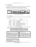
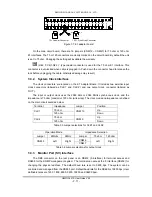
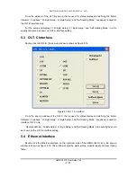
3.2.3 Optical
Interface
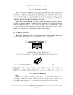
The H9MO-1641S uses a high reliability optical transceiver device with SC connector. It is
equipped with 3 sets of optical connectors (labeled A, B and C) and ‘Tx’ for the optical signal
output and ‘Rx’ for optical signal input. The OLT-A has a built-in interface, whilst the OLT-B and
OLT-C modules are an option depending upon the application.
There is a notch on the SC connector to ensure positive cable latching. The notch of the
OLT-A is on the top and OLT-B and OLT-C is on the bottom. Ensure that the fiber cable is inserted
correctly and that the transmit and receive end of the cable is connected correctly.
(Hint: The curvature of the cable must be at least 50 mm or more. When no cable is
inserted to the optical socket, a cover must be used.)
(Caution: Do not look at the laser connector directly. The laser may damage the eye
permanently.)
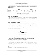
3.2.4
Service Phone Interface
The H9MO-1641S provides an RJ11 connector for the service phone line (order wire) via
the E1 overhead bit in the STM-1 frame structure. The order wire phone provides service
contact between the nodes on the network, it also functions as an input panel for the control of
the LCD display, details of which are in the next section.
The order wire can be set in hotline or dial mode via management software or through
the F interface (RS232-SV interface). In hotline mode, when any node hooks off, all nodes set
in hotline mode will ring; when it is set as dial call, the phone sets must operate in dual-tone
multi-frequency (DTMF) mode, to receive selective calls from point to point, a point to multiple
points, point to group and point to whole line.
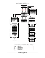
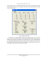
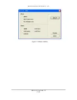
3.2.5 LCD
Display
For convenience of operation, the H9MO-1641S is provided with an LCD display which
indicates system status, clocking status, alarm message and alarm messages.
By using the order wire phone set you can access the LCD display and choose the various
options as detailed below.