


BEIJING HUAHUAN ELECTRONICS Co., LTD.
H9MO-1641S User Guide V2.2
- P.
7
-
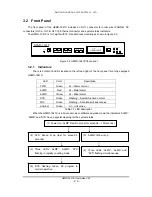
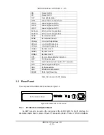
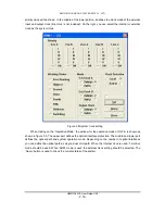
Table 3.2 LEDs indicator sequence
Stage (1), verify the SV program with program length and checksum, then go to stage (2). If
the system is in upgrade mode, stage (5) will appear. Stage (2) indicates the transfer of SV
program and uploading to the FPGA during stage (3). When into stage (4), the system is under
normal operating conditions and indicates that equipment is operating normally. The ‘ALMP’ and
‘ALMD’ may be light up depending on the status of the system.
Stage (5) and (6) indicates that the system is under Boot ROM mode which is used for
upgrading the operating software. The software upgrade is controlled by the SNMP management
system H7-GMSW. When the unit is under control and in upload mode, all 3 LEDs ‘ALMP’, ‘ALMD’
and “SYS’ will flash simultaneously. When the code is downloading, all 3 LEDs will flash ,once the
download has completed the 3 LEDs will flash simultaneously once again.
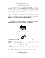
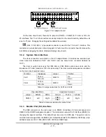
3.2.2 Ethernet
Interface
H9MO-1641S is equipped with an Ethernet interface connector (Ethernet module is an option)
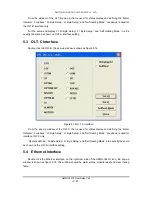
by using standard MDI-II RJ45 socket. Signal pin definition is shown in figure3.3.
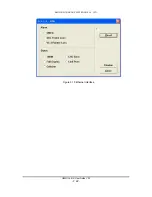
Figure 3.3 Ethernet connector pin definition
For the RJ45 connector, the pin numbering and pin assignment is shown in figure 3.4.
Fig 3.4 Pin numbering of the RJ45
plug
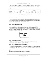
Pin
Number 1 2 3 4 5 6 7 8
Definition RxD+
RxD-
TxD+
TxD-
Table 3.3 RJ45 plug pin definition
(Hint: The 100Base-TX interface of this device is a standard MDI-X interface. For
connecting to an MDI device, such as an Ethernet LAN card, a straight through cable is used. For
connecting to MDI-X equipment, such as a hub or switch, a cross-over cable is required.)
T P O N
T P O P
TP I P
TP I N
8
1