background image

4-5

Troubleshooting

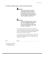
ACCESSING THE ROTOR IN CASE OF POWER FAILURE

WARNING

Any maintenance procedure requiring 
removal of a panel exposes the operator to 
the possibility of electrical shock and/or 
mechanical injury. Therefore, turn the power 
off (O) and disconnect the instrument from 
the main power source, and refer such main-
tenance to qualified service personnel.

!

WARNING

Before performing this procedure, verify that 
the rotor is not spinning by listening carefully 
for any noise coming from the chamber. 
Proceed only if the instrument is quiet. Never 
attempt to override the door interlock system 
while the rotor is spinning.

If the facility power fails only momentarily, the centrifuge will 
resume operation when the power is restored and the rotor will return 
to the set speed. In the event of an extended power failure, it may be 
necessary to override the door-locking mechanism manually to 
remove the rotor and retrieve your sample.

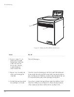
To access the door-locking mechanism, you must remove the centri-
fuge front panel. Two latches secure the front panel in place; these 
latches are accessible through two holes at the upper right and left 
of the panel (see Figure 4-1). 

Action

Result

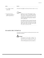
1. Turn the power switch to off 

(O) and unplug the power 
cord from the main source.

Summary of Contents for Avanti J-20 XP

Page 1: ...J320XP IM 5 Avanti J 20 XP Instruction Manual Expanded Performance Centrifuge TM TM TM MADE IN U S A ...

Page 2: ......

Page 3: ...the power switch is turned off and the instrument is disconnected from the main power source and refer such servicing to qualified personnel Be sure to use the anchoring system to secure the centrifuge in place The anchoring system is designed to reduce the possibility of injury or damage that could result from instrument movement in the event of a major rotor mishap Do not replace any centrifuge ...

Page 4: ...cautions are taken Observe all cautionary information printed on the original solution containers prior to their use Handle body fluids with care because they can transmit disease No known test offers complete assurance that they are free of micro organisms Some of the most virulent Hepatitis B and C and HIV I V viruses atypical mycobacteria and certain systemic fungi further emphasize the need fo...

Page 5: ...J320XP IM 5 May 2005 TM TM MADE IN U S A Avanti J 20 XP Instruction Manual Expanded Performance Centrifuge 2005 Beckman Coulter Inc Printed in the U S A ...

Page 6: ......

Page 7: ...l Features 1 1 Operational Features 1 2 Physical Data 1 2 Available Rotors 1 3 Preinstallation Requirements 1 7 Electrical Requirements 1 8 Single and Three Phase Power Connections 1 9 Additional Requirements for Three Phase Power Connections 1 11 Space and Location Requirements 1 12 Securing the Centrifuge to the Floor 1 12 Using J2 Series Rotors in the Avanti J 1 14 Checking for Rotor Drive Pins...

Page 8: ...Controls and Indicators 2 5 Power Switch 2 5 Control Panel 2 5 SECTION 3 OPERATION Summary of Avanti J 20XP Run Steps 3 2 Preparation and Loading 3 3 Entering Run Parameters 3 4 Selecting a Rotor 3 4 Setting Run Speed 3 4 Setting Run Time 3 6 Setting Run Temperature 3 7 Setting Acceleration and Deceleration Rates 3 8 Setting Up an Elutriation Run 3 10 Starting a Run 3 13 Changing Parameters During...

Page 9: ... 11 SECTION 5 CARE AND MAINTENANCE Maintenance 5 2 Cleaning 5 2 Decontamination 5 3 Sterilization and Disinfection 5 4 Replacing the Air Filter 5 4 Circuit Breaker and Fuses 5 5 Storage and Transport 5 5 Storage 5 5 Returning a Centrifuge 5 5 Supply List 5 6 Replacement Parts and Supplies 5 6 APPENDIX TEMPERATURE CALIBRATION PROCEDURE Warranty ...

Page 10: ... Figure 2 2 The Control Panel 2 5 Figure 3 1 Acceleration and Deceleration Settings Graph 3 9 Figure 3 2 Elutriation Controls 3 11 Figure 4 1 Emergency Door Release Latch Access 4 6 Figure 4 2 Manual Door Release 4 7 Figure 4 3 Venting the Chamber Vacuum 4 9 Figure 4 4 Front Panel Retaining Strip 4 10 Page Table 1 1 Nominal Instrument Voltage Ratings for the Avanti J 20XP 1 9 Table 1 2 Required Wi...

Page 11: ...care and maintenance We recommend that you read this entire manual especially the SAFETY NOTICE and all safety related information before operating the instrument or performing instrument maintenance Section 1 contains system specifications and instructions for preparing your site for centrifuge installation Section 2 contains an overall description of the centrifuge including a description of sys...

Page 12: ...TIONS Certain symbols are used in this manual to call out safety related and other important information These international symbols may also be displayed on the centrifuge and are reproduced and described on the inside cover and or below NOTES CAUTIONS AND WARNINGS NOTE Used to call attention to information that should be followed during installation use and or servicing of the equipment CAUTION ...

Page 13: ...ple _78 68a and _7834a appear in boxes Display field names for example TEMP C or SPEED appear in bold type RADIO INTERFERENCE This instrument has been tested and found to comply with the limits for a Class A digital device pursuant to Part 15 of FCC Rules These limits are designed to provide reasonable protection against harmful interference when the equipment is operated in a commercial environme...

Page 14: ... set out in the radio interfer ence regulations of the Canadian Department of Communications Le présent appareil numérique n émet pas de bruits radioélectriques dépassant les limites applicables aux appareils numériques de Classe A prescrites dans le reglement sur le brouillage radioelectrique édicté par le Ministère des Communications du Canada ...

Page 15: ...ous hold Time display indicates run time remaining timed run or elapsed time hold run Temperature Setting range 10 to 40 C in 1 C increments Accuracy rotor temperature controlled to within 2 C of set temperature after equilibration Ambient temperature range 16 to 38 C 60 to 100 F Cooling fluid Refrigerant 404A HFC Acceleration maximum or slow Deceleration maximum slow or off ______________ During ...

Page 16: ...l with polycarbonate coating overlay polyurethane enamel on door and covers acrylic baking enamel on other surfaces Electrical requirements 200 208 240 V single phase instrument 180 264 VAC 30 A 50 60 Hz 230 V single phase instrument 180 264 VAC 30 A 50 Hz 220 380 V plus neutral three phase instrument 313 457 VAC plus neutral 16 A 50 Hz Electrical supply Class I Maximum heat dissipation into room ...

Page 17: ... 000 rpm in the Avanti J 20XP centrifuge and 24 000 rpm in the Avanti J 30I centrifuge d In the Avanti J 20XP the JCF Z Continuous Flow Zonal Rotor can be used in the continuous flow and reorienting gradient zonal configurations only Rotor Profile and Description Max RPMa Max RCF g Max Capacity Rotor Manual Number JA 30 50 Ti Fixed Angle 34 8 place rmax 108 mm 26 000b 81 800 8 50 mL J TB 070 JA 25...

Page 18: ...nti J 30I centrifuge d In the Avanti J 20XP the JCF Z Continuous Flow Zonal Rotor can be used in the continuous flow and reorienting gradient zonal configurations only Rotor Profile and Description Max RPMa Max RCF g Max Capacity Rotor Manual Number JA 20 Fixed Angle 34 8 place rmax 108 mm 20 000 48 400 8 50 mL J TB 003 JA 18 1 Fixed Angle 24 place 45 adapter rmax 116 mm 25 adapter rmax 112 mm 18 ...

Page 19: ...nd 24 000 rpm in the Avanti J 30I centrifuge d In the Avanti J 20XP the JCF Z Continuous Flow Zonal Rotor can be used in the continuous flow and reorienting gradient zonal configurations only Rotor Profile and Description Max RPMa Max RCF g Max Capacity Rotor Manual Number JA 12 Fixed Angle 35 12 place rmax 144 mm 12 000 23 200 12 50 mL J TB 051 JA 10 Fixed Angle 25 6 place rmax 158 mm 10 000 17 7...

Page 20: ...anti J 30I centrifuge d In the Avanti J 20XP the JCF Z Continuous Flow Zonal Rotor can be used in the continuous flow and reorienting gradient zonal configurations only Rotor Profile and Description Max RPMa Max RCF g Max Capacity Rotor Manual Number JS 24 38 Swinging Bucket 6 place rmax 161 mm 10 000c 18 000 6 38 5 mL J TB 058 JS 24 15 Swinging Bucket 6 place rmax 171 3 mm 10 000c 19 200 6 15 mL ...

Page 21: ...all this instrument Its purchase price includes installation by Beckman Coulter personnel Installation by anyone other than an authorized Beckman Coulter representative invalidates any warranty covering the instrument Preinstallation requirements have been sent prior to shipment of the instrument The following information is provided in case the centrifuge must be relocated The centrifuge will be ...

Page 22: ...er at a power source known to be clear of erratic loads spikes and electromagnetic interference Make sure that there are properly rated thermal circuit breakers at the service panel to protect the centrifuge circuit If fuses must be used instead of the specified circuit breakers the fuses may require a rating of greater than 30 amperes for single phase centrifuges or greater than 16 amperes for th...

Page 23: ...centrifuges including earth ground and two power leads with 30 ampere circuit breakers Figure 1 2 shows the power connection for three phase centrifuges including earth ground and three power leads with minimum 16 ampere circuit breakers and common neutral connection Table 1 2 contains wiring information Nominal Instrument Voltage Rating Instrument Part Number Instrument Part Number Elutriation Sy...

Page 24: ...d North American Green Yellow Earth ground Light Blue Neutral N L Brown Live or Line L L Black three phase connections only Live or Line qty 2 L Measured Line Voltage Wall Outlet Hubbell 9330 Bryant 96 30 FR or Equivalent NEMA 6 30 R Earth Ground 30 ampere Circuit Breaker 30 ampere Circuit Breaker Measured Line Voltage Phase to Phase Earth Ground 16 ampere Circuit Breaker 16 ampere Circuit Breaker...

Page 25: ...s during the start period at low line voltage see Figure 1 3 for the acceptable voltage ranges The mains power for the centrifuge must be of sufficient wire gauge to provide this condition The wire gauge required at a particular site must be determined by a facilities engineer at that site Figure 1 3 Correct and Incorrect Three Phase Power Configurations The centrifuge can tolerate a drop of 15 vo...

Page 26: ... good ventilation away from heat producing laboratory equipment If ambient temperature exceeds 38 C 100 F premature component failure may result WARNING Do not place the centrifuge near areas containing flammable reagents or combustible fluids Vapors from these materials could enter the instrument s air system and be ignited SECURING THE CENTRIFUGE TO THE FLOOR Avanti J series centrifuges are cert...

Page 27: ... and Dimensions NOTE Beckman Coulter representatives are not equipped to drill holes in your floor The holes must be drilled before your scheduled installation cm in 6 0 ft 1 8 m 6 25 16 0 116 45 5 149 58 5 86 34 86 34 71 28 Air Exit Depth Air Intake Air Diverter Power Cable ...

Page 28: ...otor pins are positioned parallel to the BECKMAN name engraved at the center of the rotor body see Figure 1 5 Knowing the pin orientation before you install the rotor will help to ensure that you position the rotor properly on the hub minimizing the chance of hub damage Check all J2 series rotors for drive pins before using them in an Avanti J series centrifuge and do not use rotors without drive ...

Page 29: ...nd assembly instructions This kit is for use with Cole Parmer tubing size 16 6 4 mm 1 4 in O D the tubing size most commonly used with the JCF Z rotor Two additional kits are available one which contains adapters for size 14 tubing 4 8 mm 3 16 in O D and one which contains adapters for size 15 tubing 9 6 mm 3 8 in O D If you wish to use either of these sizes of tubing you will need to purchase one...

Page 30: ...ave not been modified at the factory When the bearings in the JCF Z rotating seal assembly get old or worn the resulting drag on the bearings changes the rotor s dynamic properties making them similar to those of several Beckman Coulter fixed angle rotors If rotor misidentification occurs when your JCF Z rotor is used first perform three runs from 0 to 5000 rpm and back to 0 rpm If rotor misidenti...

Page 31: ...fications and Preinstallation Requirements NOTE If the JCF Z rotor is misidentified the run speed will be limited to the maximum speed for the identified rotor The maximum speed for the JCF Z rotor is 20 000 rpm ...

Page 32: ...ogether with the Beckman Coulter rotors designed for use in this centrifuge applications include Routine processing such as sample preparations pelleting extractions purifications concentrations phase separations and spin column and spin filter centrifugations Rapid sedimentation of protein precipitates large particles and cell debris Preparation of subcellular organelles such as mitochondria nucl...

Page 33: ...S The Avanti J 20 XP centrifuge has been designed and tested to operate safety indoors at altitudes up to 2 000 m 6 562 ft Safety features include the following An electromechanical door lock system prevents operator contact with spinning rotors and prevents run initiation unless the door is shut and locked The door locks when _78 68a is pressed or when the POWER switch is turned off A steel casin...

Page 34: ...tor chamber is made of stainless steel to resist corrosion A rubber gasket around the chamber opening ensures sealing Instrument gaskets have not been qualified as bioseals for aerosol containment DRIVE The drive spindle is directly driven by a brushless high torque switched reluctance motor The instrument s resilient suspension minimizes disturbance of the sample during acceleration and deceler a...

Page 35: ...ver set temperature of the sample OVERTEMP SYSTEM An overtemp over temperature system provides sample protection and safety for the user During a run if the system temperature rises 4 C above the set temperature the TEMP diagnostic will light The run will continue unless stopped by the user If the temperature rises 8 C above the set temperature the system will shut down using maximum brake The sys...

Page 36: ...sy visibility and access It contains a digital display for actual and setup values knobs and touch keys for parameter entry and additional touch keys for system control Figure 2 2 The Control Panel START STOP ROTOR ID SPEED TIME RPM TEMP RPM RCF HR MIN C 0 00 00 20 O I START ROTOR ID SPEED TIME RPM TEMP RPM RCF SET ACTUAL SET ACTUAL TEMP C TIME HOLD RPM RCF ACCEL DECEL CLEAR MAX SLOW MAX SLOW OFF ...

Page 37: ...e elapsed since _78 68a was pressed After 3 hours 180 minutes have elapsed the timer will reset to 0 and continue counting elapsed time until _7834a is pressed Knobs and Touch Keys The rotor name speed time and temperature settings are entered by turning the appropriate knob until the required value is displayed Touch keys allow the user to start and stop the centrifuge and to select speed mode RP...

Page 38: ...ecified lengths The _ 30 a key is used to toggle between the two modes In HR MIN mode The TIME knob is used to set run time which can be set up to 3 hours and 0 minutes 180 minutes Each TIME knob increment is 1 minute A full turn of the knob equals 60 minutes The time setting can be changed during a run During a run the time remaining in the run is displayed When 0 is reached the run ends and the ...

Page 39: ...key displays the selection Acceleration rates are described in Table 3 3 in Section 3 DECELERATION Key _ 0a Used to select maximum or slow deceleration or off no brake An indicator light above the _ 0a key displays the selection Decelera tion rates are described in Table 3 4 in Section 3 System Keys _78 68a Pressed to begin a run When _78 68a is pressed the display immedi ately shows the actual ce...

Page 40: ...mic fungi further emphasize the need for aerosol protection Handle other infectious samples according to good laboratory procedures and methods to prevent spread of disease Because spills may generate aerosols observe proper precautions for aerosol containment Do not run toxic pathogenic or radioactive materials in this centrifuge without taking appropriate safety precautions Biosafe containment s...

Page 41: ...ode and turn the SPEED knob until the required RCF appears in the SPEED display 5 Turn the TIME knob until the required run length appears in the TIME display Or press for continuous operation 6 Turn the TEMP knob until the required temperature appears in the TEMP C display 7 Press _ 0a repeatedly to select MAX maximum or SLOW acceleration 8 Press _ 0a repeatedly to select MAX maximum or SLOW dece...

Page 42: ...uckets If you are using a J Lite rotor with cannisters place a cannister in each rotor body cavity CAUTION Do not drop the rotor onto the drive hub The drive shaft can be bent if the rotor is forced side ways or dropped onto the hub Install the rotor by centering it over the hub and carefully lowering it straight down 4 Securely attach the rotor lid knob or tie down knob in rotors without lids to ...

Page 43: ... ENTERING RUN PARAMETERS SELECTING A ROTOR Action Result Turn the ROTOR knob until the rotor in use appears in the display Small green LEDs by each rotor type abbreviation light one at a time and the rotors of that type appear consecutively in the display SETTING RUN SPEED Enter a run speed up to 26 000 rpm or up to the maximum speed of the rotor in use Or enter a relative centrifugal field RCF va...

Page 44: ...ghts 3 Turn the SPEED knob until the required RPM appears in the SPEED display When the run is started the centrifuge operates at the set speed The corresponding RCF is automatically calculated Press to display the RCF value Setting RCF Action Result 1 Check to see if the red RCF light is lit on the display If it is lit go to step 3 2 Press the key to select the RCF mode On the display the red RCF...

Page 45: ...default Timed Run Action Result 1 Turn the TIME knob until the required run time appears in the TIME display If you enter more than 59 minutes in the minutes field the system automatically converts the entry to hours and minutes after _ 28 6a is pressed 2 When all run parameters are entered press _78 68a The rotor begins to accelerate and the display begins showing the remaining run time The run w...

Page 46: ...0 minutes and then will reset to 0 and continue counting 3 Press _7834a to end the run The rotor decelerates to a stop SETTING RUN TEMPERATURE Select a run temperature between 10 and 40 C in 1 C increments NOTE For runs at temperatures other than ambient always refrigerate or warm the rotor to the required run temperature before the run For low temperature runs precool the system by running a prec...

Page 47: ...cedure provided in the Appendix SETTING ACCELERATION AND DECELERATION RATES Tables 3 1 and 3 2 describe the acceleration and deceleration settings Figure 3 1 provides a graphic representation of these settings Table 3 1 Acceleration Settings TEMP C 1 During transient conditions such as acceleration and deceleration rotor temperature may be outside this range C TEMP 20 Maximum Acceleration Slow Acc...

Page 48: ...d during the last few rpm until 0 is reached to minimize disturbance of the sample Reduced torque is used from set speed to 500 rpm causing deceleration to 500 rpm to take twice as long as maximum deceleration The exact rate depends on the mass of the rotor in use Larger rotors will take longer Deceleration time from 500 to 0 rpm is approxi mately 2 minutes larger rotors take longer No brake is us...

Page 49: ...MAX SLOW and OFF deceleration settings The selected setting lights SETTING UP AN ELUTRIATION RUN Centrifuges equipped for elutriation have elutriation controls as shown in Figure 3 2 along with a view port in the door and an elutri ation power box mounted on the back of the control panel See the JE 5 0 elutriator rotor manual JE5 IM for complete rotor setup and operating instructions ACCEL MAX SLO...

Page 50: ...les at the left side of the door seal Close the centrifuge door 3 Turn the ROTOR knob to the JE position 5 0 appears in the ROTOR ID display 4 Enter the remaining run parameters Refer to the JE 5 0 rotor manual for rotor setup and operating instructions The run is ready to begin START STOP ROTOR ID SPEED TIME RPM TEMP RPM RCF HR MIN C 0 00 00 20 DELAY ELUTRIATOR DELAY ELUTRIATOR ROTOR JSP JS JA JL...

Page 51: ...tor is synchronized with the strobe The chamber will appear to be motionless Sample can now be injected into the lines See the rotor instruction manual for detailed instructions NOTE At the end of the run after disassembling the liquid and power lines be sure to replace the black rubber stoppers in the ports at the left side of the centrifuge door Failure to seal these openings will prevent proper...

Page 52: ... rotor are the same If the system detects that the installed rotor is not the rotor that the user selected with the ROTOR knob and the speed selected by the user is greater than the installed rotor s maximum permitted speed the system will reduce the run speed to the maximum allowed for the installed rotor CHANGING PARAMETERS DURING A RUN While a run is in progress the speed time temperature and a...

Page 53: ...d press _78 68a The system will ignore any elapsed time To change from HR MIN mode to HOLD mode press the key The display will show the total accumulated run time and will begin counting the time elapsed from that point To change from HOLD mode to HR MIN mode press the key and turn the TIME knob until the run length appears in the display Press _78 68a The system will ignore any elapsed time and w...

Page 54: ...locations around the door opening and depress the foot pedal again To minimize icing remove moisture from inside the chamber from the chamber gasket and from the inner door surface before each run by wiping these surfaces with a clean cloth Also keep the door closed as much as possible UNLOADING THE CENTRIFUGE At the end of a run unload the rotor following the instructions in the applicable rotor ...

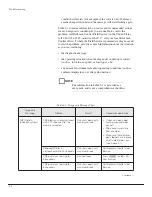
Page 55: ...tic messages the probable causes and the recommended actions Two kinds of diagnostic conditions can occur Cautionary diagnostic messages alert you to a condition that may need attention when the run is complete Cautionary diagnostic messages provide information only they do not shut down the run in progress Press _ 0 6a to stop the light from flashing If the condition still exists the diagnostic m...

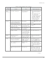
Page 56: ...al and or operating conditions such as ambient temperature or voltage fluctuations NOTE The information in Table 4 1 is provided as a user guide and is not a comprehensive checklist Table 4 1 Diagnostic Message Chart Continued Diagnostic Message Problem Result Recommended Action FRS friction reduction system FRS integrity is not established within 10 seconds after the pump is turned on Run shuts d...

Page 57: ...tor rotor ID system malfunction Run shuts down with maximum brake Check rotor and restart run No rotor in chamber Run starts within seconds the system determines that no rotor is installed and the run shuts down with maximum brake Install rotor and restart run SPEED Speed control system is malfunctioning Rotor spinning above set speed run shuts down with maximum brake Call Beckman Coulter Field Se...

Page 58: ...sound is coming from the chamber indicating a spinning rotor Follow the directions under ACCESSING THE ROTOR IN CASE OF POWER FAILURE below REFR refrigeration system Refrigeration system malfunctioning Run shuts down with maximum brake Call Beckman Coulter Field Service TEMP System temperature goes above 4 C or below 2 C of set temperature after set temperature is reached Run continues TEMP displa...

Page 59: ...trument is quiet Never attempt to override the door interlock system while the rotor is spinning If the facility power fails only momentarily the centrifuge will resume operation when the power is restored and the rotor will return to the set speed In the event of an extended power failure it may be necessary to override the door locking mechanism manually to remove the rotor and retrieve your sam...

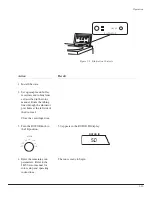
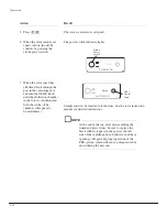
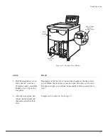
Page 60: ...nd latch disengages the front panel will fall forward about an inch from the top The bottom of the front panel is held in place by three grooved brackets attached to the front panel that seat over a metal retaining strip on the centrifuge bottom panel 4 Lift the front panel up and off the centrifuge set it aside You will see an inner front panel that extends about halfway down from the centrifuge ...

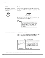
Page 61: ...mber at the time of the power failure the door may or may not open If it opens go to step 6 If it does not open you will need to manually vent the vacuum Go to step 7 6 After the door opens first release the foot pedal and then release the interlock lever Sample can be removed Go to step 10 START STOP ROTOR ID SPEED TIME RPM TEMP RPM RCF HR MIN C 0 00 00 20 Retaining Strip Manual Door Release Inte...

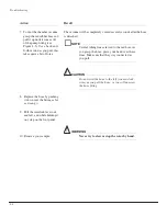
Page 62: ...d NOTE Several tubing lines are tied to the red hose As you grasp the hose place your hand over these lines Make sure that they stay connected as you pull CAUTION Do not twist the hose to the left counterclock wise as you pull the hose or you will unscrew the hose fitting 8 Replace the hose by pushing it down over the fitting as far as it can go 9 Pull the interlock lever out and left and while ho...

Page 63: ...9 Troubleshooting Figure 4 3 Venting the Chamber Vacuum Vacuum Pump Grasp red hose and pull up Do not disconnect the tubing lines tied to the red hose Red hose removed from fitting Replace red hose 1 2 3 ...

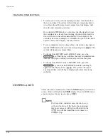
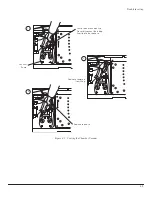
Page 64: ...side of the door over the front panel retaining strip see Figure 4 4 Push the top of the front panel into place Figure 4 4 Front Panel Retaining Strip 2 Hold the left top edge in place and insert the Allen wrench through the hole Turn to the right clockwise about one half turn until you reach a stop The latch engages 3 Repeat step 2 on the right side The second latch engages Retaining Strip ...

Page 65: ...ry installed magnets On the first few uses of a new JCF Z rotor or in an older JCF Z rotor with newly replaced bearings run the rotor from 0 to 5000 rpm and back to 0 rpm three times This procedure will distribute lubricant around the bearings in the rotating seal assembly reducing drag In older JCF Z rotors with bearings that have not been replaced recently follow the same procedure as for a new ...

Page 66: ...It is your responsibility to decontaminate the instrument as well as any rotors and accesso ries before requesting service by Beckman Coulter Field Service WARNING Any maintenance procedure or servicing of this equipment that requires removal of any covers can expose parts which involve the risk of electric shock or personal injury Make sure that the power switch is off O and the centrifuge is dis...

Page 67: ...hat may be adjusted as appropriate for your laboratory conditions CLEANING Clean the centrifuge frequently Always clean up spills when they occur to prevent corrosives or contaminants from drying on compo nent surfaces NOTE Before using any cleaning or decontamination methods except those recommended by the manufacturer users should check with the manufacturer that the proposed method will not dam...

Page 68: ...arp glass fragments may be embedded in their surfaces Examine the chamber gasket to make sure that no glass particles are retained in it Carefully remove any glass particles that may remain Carefully wipe away any glass particles that remain in the chamber DECONTAMINATION If the instrument and or accessories are contaminated with radioac tive or pathogenic solutions perform all appropriate safety ...

Page 69: ...k the air filter regularly and replace it about once a year or more often if it looks dirty The air filter is not fastened to the centrifuge so no tools are required for removal or installation 1 To remove the air filter hold the side edges and lift the filter straight up until the bottom edge is above the centrifuge bottom retaining strip Pull the filter out bottom edge first and discard it 2 Ins...

Page 70: ...rage Temperature and humidity conditions for storage should meet the environmental requirements described under SPECIFICATIONS RETURNING A CENTRIFUGE Before returning a centrifuge or accessory for any reason prior permission a Returned Goods Authorization form must be obtained from Beckman Coulter Inc Contact your local Beckman Coulter office to obtain the RGA form and instructions for packaging a...

Page 71: ...kman Solution 555 1 qt 339555 Zonal Bracket Kit for Cole Parmer size 16 tubing 6 4 mm 1 4 in O D 366431 Zonal Bracket qty 1 366430 Thumbscrew stainless steel M4 threads 19 mm qty 2 893412 Thumbscrew stainless steel M4 threads 12 mm qty 2 893411 Cable Clamp nylon 6 4 mm 1 4 in I D qty 10 000499 Zonal Tubing Adapter for Cole Parmer size 14 tubing 4 8 mm 3 16 in O D 363844 Note kit 366431 is also req...

Page 72: ...ture setting to bring your sample as close as possible to the required temperature 1 For runs at other than ambient temperature precool or prewarm the rotor and test samples to the required temperature The length of precooling prewarming time depends on how different the rotor starting temperature is from the required run temperature 2 Install the rotor with adapters if applicable and tubes or bot...

Page 73: ...ometer or thermocouple 6 If the measured and set temperatures are different note how many degrees different they are and adjust the set temperature up or down that number of degrees For example If the required sample temperature is And the measured buffer water temperature is Set the temperature to 4 C 6 C 2 C 5 C 4 C 6 C ...

Page 74: ...rned to Buyer with the trans portation charges collect unless the product is found to be defective in which case Beckman Coulter will pay all trans portation charges Beckman Coulter makes no warranty concerning products or accessories not manufactured by it In the event of failure of any such product or accessory Beckman Coulter will give reasonable assistance to the Buyer in obtaining from the re...

Page 75: ...d Section 2 Taipei 106 Taiwan Republic of China Telephone 886 2 2378 3456 Fax 886 2 2377 0408 TURKEY Beckman Coulter Ltd E 5 Yanyol Faith Cad 81410 Soganlik Kartal Istanbul Turkey Telephone 90 216 309 1900 Fax 90 216 309 0090 UNITED KINGDOM Beckman Coulter United Kingdom Ltd Oakley Court Kingsmead Business Park London Road High Wycombe Buckinghamshire HP11 1JU England U K Telephone 01494 441181 Fa...

Reviews: