


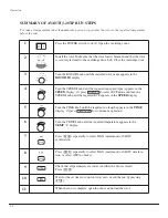


2-5
Description
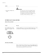
CONTROLS AND INDICATORS
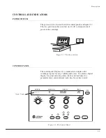
POWER SWITCH
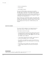
The power switch is located below the control panel (see Figure 2-1).
This two-position rocker switch (I, on; O, off) controls electrical
power to the centrifuge.
Figure 2-1. The Power Switch
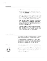
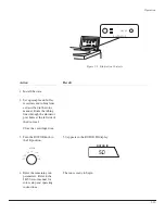
CONTROL PANEL
The control panel (Figure 2-2) is mounted at an angle on the
centrifuge top rear for easy visibility and access. It contains a digital
display for actual and setup values, knobs and touch keys for
parameter entry, and additional touch keys for system control.
Figure 2-2. The Control Panel
START
STOP
ROTOR ID
SPEED
TIME
RPM
TEMP
RPM/RCF
HR:MIN
°C
– – –
0
00:00
20
O
I
START
ROTOR ID
SPEED
TIME
RPM
TEMP
RPM/RCF
SET
ACTUAL
SET/
ACTUAL
TEMP °C
TIME/
HOLD
RPM/
RCF
ACCEL
DECEL
CLEAR
MAX
SLOW
MAX
SLOW
OFF
FRS
ROTOR
IMBAL
SPEED
DOOR
SYS
POWER
DRIVE
REFR
TEMP
HR:MIN
STOP
– – –
0
00:00
20
TIME
SPEED
ROTOR
JCF
JSP
JV
JS
JLA
JA
JE
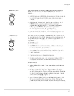
Digital Display
TM


