


Operation
EL2912
23
Version: 1.0.0
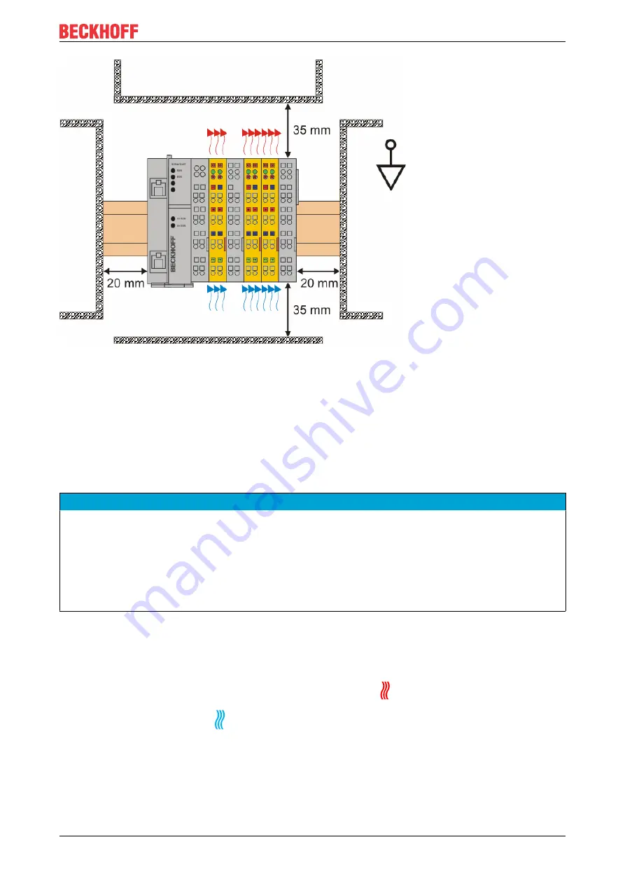
Fig. 8: Installation position and minimum distances
In order to ensure optimum convection cooling, the distances to neighboring devices and to control cabinet
walls must not be smaller than those shown in the diagram.
4.2.3.4
Temperature measurement
The temperature measurement consists of an EK1100 EtherCAT Coupler, to which EtherCAT Terminals are
attached, based on the typical distribution of digital and analog signal types at a machine. On the EL6910 a
safety project is active, which reads safe inputs and enables safe outputs during the measurement.
NOTE
External heat sources / radiant heat / impaired convection
The maximum permissible ambient temperature of 55°C was checked with the example configuration de-
scribed above. Impaired convection, an unfavorable location near heat sources or an unfavorable configu-
ration of the EtherCAT Terminals may result in overheating of the TwinSAFE components.
The key parameter is always the maximum permitted internally measured temperature of 110°C, above
which the TwinSAFE components switch to safe state and report an error. The internal temperature can be
read from the TwinSAFE components via CoE.
4.2.3.5
Notes on the configuration of TwinSAFE components
The following notes illustrate favorable and unfavorable terminal arrangements from a thermal perspective.
Components with higher waste heat are identified with a red symbol
, components with lower waste heat
are identified with a blue symbol
.
EK11xx EtherCAT Coupler and EL9410 power supply terminal
The more terminals are attached after an EtherCAT Coupler or a power supply terminal, the higher the E-bus
current that their power supply units have to supply. With increasing current the waste heat from the power
supply units also increases.
Summary of Contents for TwinSAFE EL2912
Page 2: ......
Page 53: ...Appendix EL2912 53 Version 1 0 0 5 2 Certificates ...


