Mounting and wiring
KL3311, KL3312, KL3314 and KL3302
25
Version: 4.2
3.6
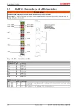
KL3312, KL3302 - Connection and LED Description
WARNING
Risk of injury through electric shock and damage to the device!
Bring the Bus Terminals system into a safe, de-energized state before starting mounting, disassembly or
wiring of the Bus Terminals!
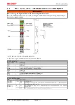
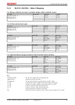
Fig. 14: KL3312, KL3302 - Connection and LEDs
KL3302 is no longer available and was replaced with KL3312.
KL3312 - Connection
Terminal point
No.
Comment
+TC1
1
Input +TC1
-TC1
2
Input -TC1
GND
3
Ground (internally connected with terminal point 7)
Shield
4
Shield (internally connected to terminal point 8)
+TC2
5
Input +TC2
-TC2
6
Input -TC2
GND
7
Ground (internally connected with terminal point 3)
Shield
8
Shield (internally connected to terminal point 4)
KL3312 - LED Description
LED
Color
Description
Run1 LED,
Run2 LED
green
On:
Normal operation
Off:
Watchdog timer overflow has occurred. If no process data is transmitted to the Bus Coupler for
100 ms, the green LEDs go out
Error1 LED
Error2 LED
red
On
Wire breakage. The resistance is in the invalid range of the characteristic curve of the respective
thermocouple.
Off
The resistance is in the valid range of the characteristic curve


