background image

Access from the user program

KL3311, KL3312, KL3314 and KL3302

34

Version: 4.2

5

Access from the user program

5.1

KL331x, KL3302 - Terminal Configuration

The terminal can be configured and parameterized via the internal register structure. Each terminal channel
is mapped in the Bus Coupler. Mapping of the terminal data in the Bus Coupler memory may differ,
depending on the Bus Coupler type and the set mapping configuration (e.g. Motorola/Intel format, word
alignment etc.). For parameterizing a terminal, the control and status byte also has to be mapped.

BK2000 Lightbus Coupler

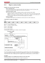
In the BK2000 Lightbus Coupler, the control/status byte is always mapped, in addition to the data bytes. This
is always located in the low byte at the offset address of the terminal channel.

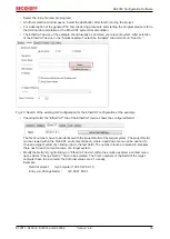
Fig. 21: Mapping in the Lightbus Coupler - example for KL3312, KL3302

BK3000 Profibus Coupler

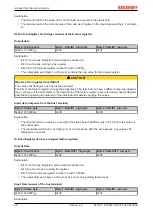
For the BK3000 Profibus Coupler, the master configuration should specify for which terminal channels the
control and status byte is to be inserted. If the control and status byte are not evaluated, the terminals
occupy 2 bytes per channel:

• KL3311: 2 bytes of input data

• KL3312 (KL3302): 4 bytes of input data

• KL3314: 8 bytes of input data

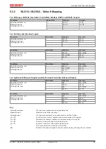
Fig. 22: Mapping in the Profibus Coupler - example for KL3312, KL3302

Summary of Contents for KL3302

Page 1: ...Documentation KL3311 KL3312 KL3314 and KL3302 Single Dual and Four Channel Analog Imput Terminals for Thermocouples 4 2 2019 10 08 Version Date...

Page 2: ......

Page 3: ...cription 25 3 7 KL3314 Connection and LED description 26 3 8 Connection of ground shield und earthing 27 3 9 ATEX Special conditions standard temperature range 28 3 10 ATEX Documentation 29 4 KS2000 C...

Page 4: ...Table of contents KL3311 KL3312 KL3314 and KL3302 4 Version 4 2...

Page 5: ...he modification of products that have already been supplied may be made on the basis of the data diagrams and descriptions in this documentation Trademarks Beckhoff TwinCAT EtherCAT EtherCAT G EtherCA...

Page 6: ...ended for trained specialists in control automation and drive engineering who are familiar with the applicable national standards Description of instructions In this documentation the following instru...

Page 7: ...08 3B 04 3H 07 3D 04 KL3302 is no longer available and was replaced with KL3312 The firmware and hardware versions delivery state of the terminal can be found in the serial number printed on the side...

Page 8: ...mum length according to the table below If the information is shorter spaces are added to it The data under positions 1 to 4 are always available The following information is contained Item no Type of...

Page 9: ...eight characters that will replace all other serial number systems at Beckhoff in the long term e g batch designations on IO components previous serial number range for safety products etc The BTN wil...

Page 10: ...an operate thermocouples using 2 wire technique Linearization over the full temperature range is realized with the aid of a microprocessor The temperature range can be selected freely The error LEDs i...

Page 11: ...sation Vibration shock resistance conforms to EN 60068 2 6 EN 60068 2 27 see also Installation instructions for enhanced mechanical load capacity 19 EMC immunity emission conforms to EN 61000 6 2 EN 6...

Page 12: ...s of nickel chrome and nickel respectively By adapting the equation according to Tm the sought after temperature can be calculated from the voltage measured across the thermocouple Based on the differ...

Page 13: ...le Off The resistance is in the valid range of the characteristic curve Process data output format In the delivery state the measured value is displayed in increments of 1 10 C in two s complement for...

Page 14: ...active Th A_h T B_h Ta A_w T B_w Tout Ta 1 7 Manufacturer and user scaling active Key Name Name Register X_ref Output value of the A D converter Tref Temperature of the cold junction Uref Voltage val...

Page 15: ...oid contact with highly insulating materials synthetic fibers plastic film etc Surroundings working place packaging and personnel should by grounded probably when handling with the devices Each assemb...

Page 16: ...l until the lock clicks onto the mounting rail If the terminals are clipped onto the mounting rail first and then pushed together without tongue and groove the connection will not be operational When...

Page 17: ...g the components The six spring contacts of the K Bus E Bus deal with the transfer of the data and the supply of the Bus Terminal electronics The power contacts deal with the supply for the field elec...

Page 18: ...sulation testing or to damage on the terminal e g disruptive discharge to the PE line during insulation testing of a consumer with a nominal voltage of 230 V For insulation testing disconnect the PE s...

Page 19: ...inal segment on both sides of the mounting rail with a mechanical fixture e g an earth terminal or reinforced end clamp The maximum total extension of the terminal segment without coupler is 64 termin...

Page 20: ...series The pluggable connection level enables the complete wiring to be removed as a plug connector from the top of the housing for servicing The lower section can be removed from the terminal block b...

Page 21: ...ve conductors and conductors with a wire end sleeve can be inserted directly into the spring loaded terminal point without tools Wiring HD Terminals The High Density HD Terminals of the ELx8xx and KLx...

Page 22: ...rnately don t toggle 2 The wire can now be inserted into the round terminal opening without any force 3 The terminal point closes automatically when the pressure is released holding the wire securely...

Page 23: ...0 08 1 5 mm2 Wire size width fine wire conductors 0 25 1 5 mm2 Wire size width conductors with a wire end sleeve 0 14 0 75 mm2 Wire size width ultrasonically bonded conductors only 1 5 mm2 Wire stripp...

Page 24: ...ly connected with terminal point 7 Shield 4 Shield internally connected to terminal point 8 n c 5 Not used n c 6 Not used GND 7 Ground internally connected with terminal point 3 Shield 8 Shield intern...

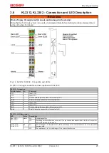
Page 25: ...TC1 GND 3 Ground internally connected with terminal point 7 Shield 4 Shield internally connected to terminal point 8 TC2 5 Input TC2 TC2 6 Input TC2 GND 7 Ground internally connected with terminal po...

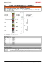
Page 26: ...Bus Terminals Fig 15 KL3314 Connection and LEDs KL3314 Connection Terminal point No Comment TC1 1 Input TC1 TC1 2 Input TC1 TC3 3 Input TC3 TC3 4 Input TC3 TC2 5 Input TC2 TC2 6 Input TC2 TC4 7 Input...

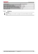
Page 27: ...on the type of thermocouple used For earthed thermocouples ground is connected to the shield If the thermocouple has no earth connection the ground shield and TC1 or TC2 contacts are connected with ea...

Page 28: ...nst the rated operating voltage being exceeded by more than 40 due to short term interference voltages The individual terminals may only be unplugged or removed from the Bus Terminal system if the sup...

Page 29: ...ration of the Beckhoff terminal systems in potentially explosive ar eas ATEX Pay also attention to the continuative documentation Notes about operation of the Beckhoff terminal systems in potentially...

Page 30: ...the Fieldbus Box Modules can be prepared before the commissioning phase Later on this configuration can be transferred to the terminal station in the commissioning phase by means of a download For doc...

Page 31: ...ldbus protocol always has the higher priority in this case 4 2 Sample program for KL register communication via EtherCAT on KL3314 exemplary Using the sample programs This document contains sample app...

Page 32: ...present coupler e g BK1120 or embedded PC KL3314 KL9010 Download https infosys beckhoff com content 1033 kl331x_kl3302 Resources zip 5996114571 zip Preparations for starting the sample programs tnzip...

Page 33: ...EtherCAT configuration of the example Checking NetId the EtherCAT tab of the EtherCAT device shows the configured NetId The first 4 numbers have to be identical with the project NetId of the target sy...

Page 34: ...e also has to be mapped BK2000 Lightbus Coupler In the BK2000 Lightbus Coupler the control status byte is always mapped in addition to the data bytes This is always located in the low byte at the offs...

Page 35: ...on Mapping in the Bus Coupler contains an overview of possible mapping configurations depending on the configurable parameters Parameterization with KS2000 The KS2000 configuration software can be use...

Page 36: ...t Coupler and Bus Terminal Controller BCxxxx BXxxxx Conditions Word offset High byte Low byte Complete evaluation yes Motorola format no Word alignment yes 0 Res Ch0 CB SB 1 Ch0 D1 Ch0 D0 2 3 Conditio...

Page 37: ...htbus Ethernet Coupler and Bus Terminal Controller BCxxxx BXxxxx Conditions Word offset High byte Low byte Complete evaluation yes Motorola format no Word alignment yes 0 Res Ch0 CB SB 1 Ch0 D1 Ch0 D0...

Page 38: ...0 D0 Ch0 CB SB 1 Ch1 CB SB Ch0 D1 2 Ch1 D1 Ch1 D0 3 Ch2 D0 Ch2 CB SB 4 Ch3 CB SB Ch2 D1 5 Ch3 D1 Ch3 D0 Conditions Word offset High byte Low byte Complete evaluation yes Motorola format yes Word align...

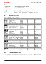
Page 39: ...40 Command register not used 0x0000 R R8 40 Terminal type e g 3312 R ROM R9 40 Software version number 0x R ROM R10 40 Multiplex shift register 0x0218 0130 R ROM R11 40 Signal channels 0x0218 R ROM R1...

Page 40: ...ber of multiplexed shift registers and their length in bits The Bus Coupler sees this structure R11 Signal channels Related to R10 this contains the number of channels that are logically present Thus...

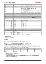
Page 41: ...00 This register contains the offset of the manufacturer linear equation equation 1 6 14 The linear equation is enabled via register R32 R20 Manufacturer scaling gain A_h 16 bit signed integer 2 8 0x0...

Page 42: ...1000 C 0 1 0 0 Type T 100 C to 400 C 0 1 0 1 Type N 100 C to 1300 C 0 1 1 0 Type U 25 C to 600 C 0 1 1 1 Type B 600 C to 1800 C 1 0 0 0 Type R 0 C to 1700 C 1 0 0 1 Type S 0 C to 1700 C Output in V R...

Page 43: ...ains various status bits of the analog input channel Status byte Bit 7 0bin Bit 6 1bin Error general error bit Bit 5 to bit 2 reserved Bit 1 1bin Overrange Bit 0 1bin Underrange Compensation The termi...

Page 44: ...e register and cold junction temperature compensation must be active R32 0x1006 type K With short circuited inputs 0 V the temperature of the terminal contacts is determined and the temperature output...

Page 45: ...nowledgment see example Bit 0 to 5 Address The address of the register to be addressed is entered in bits 0 to 5 of the control byte Control byte in register mode REG 1 MSB REG 1 W R A5 A4 A3 A2 A1 A0...

Page 46: ...used Status byte Value 0x00 0x00 0x00 0x9F 5 6 Examples of Register Communication The numbering of the bytes in the examples corresponds to the display without word alignment 5 6 1 Example 1 reading t...

Page 47: ...y the register number 31 with 01 1111bin The output data word byte 1 and byte 2 contains the code word 0x1235 for deactivating write protection Input Data answer of the bus terminal Byte 0 Status byte...

Page 48: ...terminal Refer to the description of the feature register of your terminal chapter Register description regarding the meaning of the individual bits before changing the values Input data response fro...

Page 49: ...set means Register communication switched on Bit 0 6 set means writing to the register Bits 0 5 to 0 0 specify the register number 31 with 01 1111bin The output data word byte 1 and byte 2 contains 0x...

Page 50: ...ation for Beckhoff components there Beckhoff Headquarters Beckhoff Automation GmbH Co KG Huelshorstweg 20 33415 Verl Germany Phone 49 5246 963 0 Fax 49 5246 963 198 e mail info beckhoff com Beckhoff S...

Page 51: ...point 22 Fig 13 KL3311 Connection and LEDs 24 Fig 14 KL3312 KL3302 Connection and LEDs 25 Fig 15 KL3314 Connection and LEDs 26 Fig 16 KL3312 Connection of ground shield und earthing left earthed ther...

Reviews: