Product overview
KL3311, KL3312, KL3314 and KL3302
13
Version: 4.2
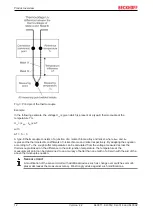
Internal conversion of the thermovoltage and the reference voltage
Since the coefficients are determined at a reference temperature of 0°C, it is necessary to compensate for
the effect of the reference temperature. This is done by converting the reference temperature into a
reference voltage that depends on the type of thermocouple, and adding this to the measured
thermovoltage. The temperature is found from the resulting voltage and the corresponding characteristic
curve.
U
k
= U
m
+ U
r
T
out
= f(U
k
)
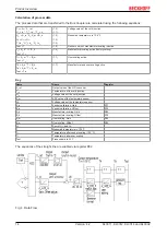
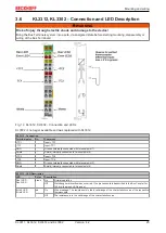
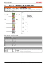
The four LEDs indicate the operating state of the associated terminal channels.
• green Run LEDs: RUN (not applicable for KL3314)
◦ On: normal operation
◦ Off: Watchdog timer overflow has occurred. If no process data are transmitted by the Bus Coupler
for 100 ms, the green LEDs go out.
• Red LEDs: ERROR
◦ On: Wire breakage. The resistance is in the invalid range of the characteristic curve of the
respective thermocouple.
◦ Off: The resistance is in the valid range of the characteristic curve.
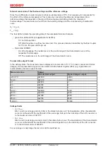
Process data output format
In the delivery state, the measured value is displayed in increments of 1/10 °C in two's complement format
(integer). Other presentation types can be selected via the feature register (R32) (e.g. signed amount
representation, Siemens output format).
Measured value
Output
Hexadecimal output
Signed integer output
-200.0 °C
0xF830
-2000
100.0 ℃
0xFC18
-1000
0.1 ℃
0xFFFF
-1
0.0 ℃
0x0000
0
0.1 ℃
0x0001
1
100.0 ℃
0x03E8
1000
200.0 ℃
0x07D0
2000
500.0 ℃
0x1388
5000
850.0 ℃
0x2134
8500
1,000.0 ℃
0x2710
10000
Voltage limits
• U
k
> U
kmax
:
Bits 1 and 6 (overrange and error bits) in the status byte are set. The linearization of the characteristic
curve is continued with the coefficients of the overrange limit up to the limit stop of the A/D converter or
to the maximum value of 0x7FFF.
• U
k
< U
kmin
:
Bits 0 and 6 (underrange and error bits) in the status byte are set. The linearization of the characteristic
curve is continued with the coefficients of the underrange limit up to the limit stop of the A/D converter
or to the minimum value of 0x8000.
For overrange or underrange the red error LED is switched on.


