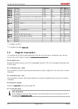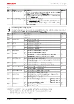
Access from the user program
KL31x2
46
Version: 2.4.0
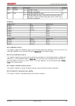
Register no.
Comment
Default value
R/W
Memory
User offset
0x0000
0
dec
R/W
SEEPROM
User gain
0x0100
256
dec
R/W
SEEPROM
Limit value 1
0x0000
0
dec
R/W
SEEPROM
Limit value 2
0x0000
0
dec
R/W
SEEPROM
Filter constants of the A/D converter, and configuration bits
for the filter
0x35C0
13760
dec
R/W
SEEPROM
R38
reserved
-
-
-
-
R39
reserved
-
-
-
-
Calibration interval *)
0x0708
1800
dec
R/W
SEEPROM
R41
reserved
-
-
-
-
...
reserved
-
-
-
-
R43
reserved
-
-
-
-
Interval for forced calibration **)
0x0003
3
dec
R/W
SEEPROM
R45
reserved
-
-
-
-
R46
reserved
-
-
-
-
Number of stable measured values
0x0032
50
dec
R/W
SEEPROM
Tolerance for measured value stability
0x0005
5
dec
R/W
SEEPROM
R49
reserved
-
-
-
-
...
reserved
-
-
-
-
R63
reserved
-
-
-
-
*) In multiples of 100 ms
**) In multiples of register
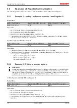
5.5
Register description
The registers are used for the parameterization of the Bus Terminals and are available for each channel.
They can be read or written by means of
R0: Raw ADC value
Register R0 contains the raw value of the analog/digital converter. This is the unchanged analog value prior
to any scaling.
R1: Calibration value - offset
After a calibration, the offset value that was determined is entered in register R1 and used for the correction
calculation.
R2: Calibration value - gain
After a calibration, the gain value that was determined is entered in register R2 and used for the correction
calculation.
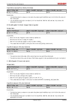
R6: Diagnostic register
is placed into register R6.
R7: Command register
User code word
For the following commands to be executed, it is first necessary for the user code word, 0x1235, to
be entered into
.


