Access from the user program
KL2532/KS2532, KL2552/KS2552
53
Version: 3.2.0
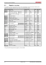
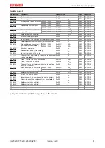
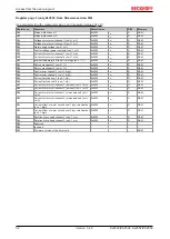
6.4
Register description
The registers are used to parameterize the DC motor output stages. They can be read or written via the
register communication and there is one instance for each terminal channel.
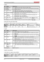
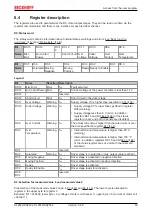
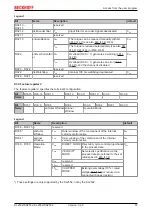
R0: Status word
The status word contains information about internal states, warnings and errors (
Bit
R0.15
R0.14
R0.1
3
R0.12
R0.11
R0.10
R0.9
R0.8
Name
Misc
Error
No Control
Power
-
Short Circuit Over
Voltage
Under
Voltage
Over
Current
Over
Temperature
Bit
R0.7
R0.6
R0.5
R0.4
R0.3
R0.2
R0.1
R0.0
Name
-
Saturated Moving
Negative
Moving
Positive
Ready Ready to Enable -
-
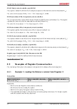
Legend
Bit
Name
Reaction Description
R0.15
Misc Error
Error
1
bin
Fault occurred
R0.14
No Control Power Error
1
bin
Control voltage at the power contacts is less than 12 V
R0.13
-
reserved
R0.12
Short Circuit
Error
1
bin
Short circuit in the driver stage
R0.11
Over Voltage
Warning
1
bin
Supply voltage 10 % higher than specified in
R0.10
Under Voltage
Warning
1
bin
• Supply voltage 80 % lower than specified in register
R36 (warning)
• Supply voltage less than 8 V (error; in addition,
registers R0.15 and bit
of the status
register are set, and both channels are disabled)
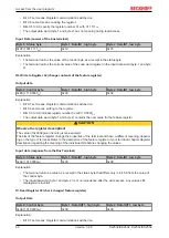
R0.9
Over Current
Warning
1
bin
The actual current was higher than the rated current over
the time specified in register
.
R0.8
Over
Temperature
Warning
1
bin
• Internal terminal temperature is higher than 80 °C
(warning)
• Internal terminal temperature is higher than 100 °C
(error; in addition, registers R0.15 and bit
of the status register are set, and both channels are
disabled)
R0.7
-
reserved
R0.6
Saturated
Warning
1
bin
Driver stage is in saturation (max. output value reached)
R0.5
Moving Negative
1
bin
Driver stage is activated in negative direction
R0.4
Moving Positive
1
bin
Driver stage is activated in positive direction
R0.3
Ready
1
bin
Driver stage is activated
R0.2
Ready to Enable
1
bin
Driver stage ready for activation
R0.0 -
R0.1
-
reserved
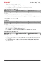
R1: Selection for measured value 1 and measured value 2
Preselection of the measured values shown in
. The lower byte is allocated to
register 2, the upper byte to register 3.
Example: R1 = 0x0602, lower byte = 2 (voltage of motor coil channel 1), upper byte = 6 (current of motor coil
channel 1).


