Mounting and wiring
EL3632
35
Version: 2.8
Additional installation instructions
For terminals with enhanced mechanical load capacity, the following additional installation instructions apply:
• The enhanced mechanical load capacity is valid for all permissible installation positions
• Use a mounting rail according to EN 60715 TH35-15
• Fix the terminal segment on both sides of the mounting rail with a mechanical fixture, e.g. an earth
terminal or reinforced end clamp
• The maximum total extension of the terminal segment (without coupler) is:
64 terminals (12 mm mounting with) or 32 terminals (24 mm mounting with)
• Avoid deformation, twisting, crushing and bending of the mounting rail during edging and installation of
the rail
• The mounting points of the mounting rail must be set at 5 cm intervals
• Use countersunk head screws to fasten the mounting rail
• The free length between the strain relief and the wire connection should be kept as short as possible. A
distance of approx. 10 cm should be maintained to the cable duct.
4.4
Positioning of passive Terminals
Hint for positioning of passive terminals in the bus terminal block
EtherCAT Terminals (ELxxxx / ESxxxx), which do not take an active part in data transfer within the
bus terminal block are so called passive terminals. The passive terminals have no current consump-
tion out of the E-Bus.
To ensure an optimal data transfer, you must not directly string together more than 2 passive termi-
nals!
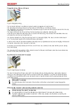
Examples for positioning of passive terminals (highlighted)
Fig. 26: Correct positioning

