background image

9

AFG Burner Manual

Figure 9. AFG Reduced Firing Rates (with LFRB)

Burner head type

Low Firing Rate Baffle installed

F0

up to 0.65 gph

F3, L1, or L2

up to 0.85 gph

F4 or F6

up to 0.90 gph

V1

up to 1.00 gph


○ Refer to 

Figure 7

 to select the mid-range nozzle 

spray angle for the head type being used.


○ Fire the burner and make sure the combustion 

is acceptable and the flame is not impinging on 

chamber surfaces.


○ If a shorter flame is needed, select a wider spray 

angle. If a longer flame is needed, select a 

narrower spray angle.


○ Either hollow or solid spray patterns may be used. 

If combustion results are not satisfactory with the 

selected spray pattern, try the other pattern.

Mount Burner on Appliance

Mounting options

1.  Bolt the burner to the appliance using the factory-

mounted flange or an adjustable flange.

Mounting dimensions

1.  When using the Beckett universal adjustable flange, 

mount the air tube at a 2° downward pitch unless 

otherwise specified by the appliance manufacturer.

2.  Verify that the air tube installed on the burner 

provides the correct insertion depth. See 

Figure 14, 

page 12

.

3.  The end of the air tube should normally be ¼” back 

from the inside wall of the combustion chamber. 

Never allow the leading edge of the head assembly 

to extend into the chamber, unless otherwise 

specified by the heating appliance manufacturer. 

Carefully measure the insertion depth when using 

an adjustable flange. Verify the insertion depth 

when using a welded flange.

Figure 7. Nozzle Spray Angles

Recommended nozzle spray angles

“F” head

70° or 80° nozzle

“L1” & “L2” head

45°, 60°, or 70° nozzle

“V1” head

45°, 60°, or 70° nozzle

The dimensions shown below are for use with L2 heads 

and M series air tube combinations ending with an ‘N’ 

suffix (example: AFG70MDAQ

N

)

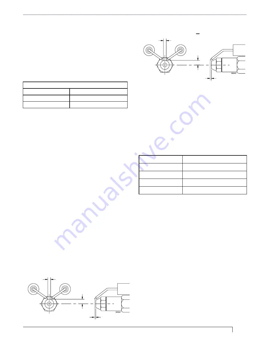
Check/adjust electrodes

Check the electrode tip settings. Adjust if necessary 

to comply with the dimensions shown in 

Figure 8

. To 

adjust, loosen the electrode clamp screw and slide/rotate 

electrodes as necessary. Securely tighten the clamp 

screw when finished.

Servicing nozzle line assembly

1.  Turn off power to burner before proceeding.
2.  Disconnect oil connector tube from nozzle line.
3.  Loosen the two screws securing igniter retaining 

clips and rotate both clips to release igniter 

baseplate. Then tilt igniter back on its hinge.

4.  Remove splined nut.
5.  “F” head air tube. - Remove nozzle line assembly 

from burner, being careful not to damage the 

electrodes or insulators while handling. To ease 

removal of long assemblies (over 9 inches), rotate 

assembly 180° from installed position after pulling 

partially out of tube.

6.  “L1”, “L2”, and “V1” head air tubes. -  Slide nozzle 

line assembly forward (further into air tube) so the 

head clears the venturi opening. Then rotate the 

nozzle line assembly 90° so the nozzle line end 

points up. Pull the nozzle line assembly toward you 

and remove assembly from burner.

Section: Mount Burner on Appliance

Figure 8. – Electrode Tip Adjustment

Standard Dimensions for F, L1, and V1 Heads.  

5/32” Gap

5/16” Above

Center

1/16” Nozzle-to-tip 

Spacing

5/32” Gap

1/4” Above

Center

1/8” Nozzle-to-tip 

Spacing

Low Firing Rate Baffle

The AFG Low Firing Rate Baffle (LFRB) reduces the 

air flow and pressure. The LFRB is sometimes used for 

firing rates under 1.00 gph as listed in 

Figure 9

. Refer 

to the appliance manufacturer’s instructions. Do not 

omit the LFRB when specified. Omitting the baffle when 

specified or installing the baffle when not specified could 

result in impaired burner performance.

7.  To replace the nozzle assembly, reverse the above steps

Summary of Contents for AF Series

Page 1: ...this manual for future reference Incorrect installation adjustment or misuse of this burner could result in death severe personal injury or substantial property damage To the Professional Qualified Installer or Service Agency y Please read and carefully follow all instructions provided in this manual before installing starting or servicing this burner or heating system y The Installation must be m...

Page 2: ...during the summer in order to prevent condensation of moisture on the inside surface of the tank Remainder of manual to be used ONLY BY QUALIFIED SERVICE TECHNICIANS Contents General Information 3 Hazard Definitions 3 Inspect Prepare Installation Site 6 7 Inspect Chimney or Direct Vent System 6 Combustion air supply 7 Clearances to burner and appliance 7 Combustion chamber Burner retrofitting 7 Pr...

Page 3: ...ion which if not avoided could result in death or serious injury Indicates a hazardous situation which if not avoided could result in minor or moderate injury Intended to bring special attention to information but not related to personal injury or property damage Owner s Responsibility Incorrect installation adjustment and use of this burner could result in severe personal injury death or substant...

Page 4: ...ncy Frozen Plumbing and Water Damage Hazard Figure 2 Burner Specifications Capacity Note 1 AF Burner 0 40 3 00 GPH AFG Burner 0 40 3 00 GPH Refer to Figure 3 Page 5 for further information Certifications Approvals ANSI UL296 and CSA B140 0 Approved Fuels USA ASTM D396 for No1 or No 2 Heating Oil B6 B20 grades Canada No 1 Stove Oil or No 2 Furnace Oil Only SEE WARNING SECTION BELOW Electrical Input...

Page 5: ... carrier at once and file the appropriate claim When contacting Beckett for service information Please record the burner serial number and have available when calling or writing You will find the serial number on the silver label located on the left rear of the burner Refer to Figure 1 Page 3 Note ATC s for specific manufacturers are listed in the Beckett OEM Specification Guide and can also be fo...

Page 6: ... they reach the dew point The condensation will mix with the sulphur in the flue gases creating sulphuric acid The acid will attack the chimney mortar brick and clay liners causing corrosion deterioration and blockage of the chimney Eventually the blockage could prevent exhausting the flue gases Instead the flue gases could vent out the barometric damper into the living space Therefore it is stron...

Page 7: ...o separate instruction sheet s included with any outside air kit or power vent system being installed Clearances to burner and appliance Provide space around burner and appliance for easy service and maintenance Check minimum clearances against those shown by the appliance manufacturer and by applicable building codes Combustion chamber Burner retrofitting Verify that the appliance combustion cham...

Page 8: ...r s information For conversions or upgrades when information is not available for the application Section Prepare the Burner Use only nozzles having the brand flow rate gph spray angle and pattern specified by the appliance manufacturer Follow the appliance manufacturer s specifications for the required pump outlet pressure for the nozzle since this affects the flow rate y Nozzle manufacturers cal...

Page 9: ...ith L2 heads and M series air tube combinations ending with an N suffix example AFG70MDAQN Check adjust electrodes Check the electrode tip settings Adjust if necessary to comply with the dimensions shown in Figure 8 To adjust loosen the electrode clamp screw and slide rotate electrodes as necessary Securely tighten the clamp screw when finished Servicing nozzle line assembly 1 Turn off power to bu...

Page 10: ...istance to the face of the head A Beckett T501 gauge may also be used Slide the nozzle line forward or back until this dimension for F heads is 1 1 to the face of the heat shield if applicable Tighten the hex head screw to secure the escutcheon plate to the burner chassis Then tighten the splined nut and attach the oil connector tube 3 Recheck the Z dimension periodically when servicing to ensure ...

Page 11: ...end of a ruler at the leading edge of the head and using a straight edge across the end of the air tube measure the distance to the end of the tube A Beckett T501 gauge may also be used Slide the nozzle line forward or back until this dimension is 1 for V1 heads Tighten the acorn nut Tighten the hex head screw to secure the head adjusting plate to the burner chassis Then tighten the splined nut an...

Page 12: ...e in fuel line components and fuel unit damaging the equipment and preventing proper operation y Use pipe joint sealant approved for use on kerosene fuel oils and biodiesel fuels Damage to the pump could cause impaired burner operation oil leakage and appliance soot up Do Not Use Teflon Tape To further protect the fuel supply system and reduce nozzle orifice plugging with firing rates below 0 75 g...

Page 13: ...s In Canada all wiring is to be in accordance with the Canadian Electrical Code Part 1 The 7505 primary control with valve on delay pre time and burner motor off delay post time requires a constant 120 volts AC power source supplied to the BLACK wire on the control The RED wire goes to the appliance limit circuit Please note that other control manufacturers may use different wire colors for power ...

Page 14: ...the wire from the W terminal on the thermostat to the TW terminal on the control SAFETY OPERATING LIMITS L1 L2 THERMOSTAT R W TR TW YELLOW TERMINAL COLOR MOTOR ORANGE L2 MTR WHITE 52021 L1 BLACK LIMIT RED L2 WHITE BLUE W WHITE STRIPE RWB TERMINAL COLOR RWB THERMOSTAT R W SAFETY OPERATING LIMITS L1 L2 Figure 18 Interrupted Ignition Valve on Delay only no motor off delay Figure 19 Interrupted Igniti...

Page 15: ...reaches a pre set time allotment The control will then go into Hard Lockout instead of recycle This feature prevents excessive accumulation of oil in the appliance firing chamber 8 Motor Off Delay If applicable the oil solenoid valve is turned off and the control delays turning the motor off for the set motor off delay time before the control returns to standby 9 Pump Prime The igniter and motor a...

Page 16: ...prime the pump properly could result in unstable combustion hot gas puff back and heavy smoke Hot Gas Puff Back and Heavy Smoke Hazard 9 Bleed the pump until all froth and bubbles are purged If desired terminate the call for heat or hold the reset button for at least one second to exit Pump Prime mode and return to Standby 10 At the end of 4 minutes the yellow light will turn off and the control w...

Page 17: ...ck or over fire draft to the level specified by the appliance manufacturer Natural Draft Applications typically over fire draft is 0 01 or 0 02 w c Direct Venting typically may not require draft adjustment High Efficiency Positive Pressure Appliances also vary from traditional appliances see manufacturer s recommendations 3 Follow these four steps to properly adjust the burner Step 1 Adjust the ai...

Page 18: ... cutoff function Check primary control safety lockout timing Check ignition system for proper operation Inspect the vent system and chimney for soot accumulation or other restriction Clean all flue passages and flue pipe Replace corroded or damaged pipes Clean the appliance thoroughly according to the manufacturer s recommendations Check the burner performance Refer to the section Set combustion w...

Page 19: ...19 AFG Burner Manual For best performance specify genuine Beckett replacement parts Replacement Parts Air Tubes Nozzle Lines Electrodes Parts For Part Number Listing refer to page 22 ...

Page 20: ...20 Burner Mounting Flange Pedestals Mounting Flange Gasket Kit 5432 Pedestal Kit 5685 Split Mounting Flange Gasket Kit 5850 Extended Pedestal Kit 5606 For Part Number Listing refer to page 22 ...

Page 21: ...21 AFG Burner Manual Burner Accessories Solenoid Valve Kit 2182602U Burner Cover Replacement Parts Burner Cover Retrofit Kit 5207301U For Part Number Listing refer to page 22 ...

Page 22: ...it Extended X X 32 2182602U Solenoid Valve Kit Delay X X 33 5207301U Burner Cover Kit X X 33a 52642001U Replacement Cover Only X X 33b 32109BK Cover Mounting Plate X X Air Tubes Nozzle Lines Electrodes Parts Item Part Description AF AFG ATC s Complete Air Tube Combinations Refer to Figure 3 Page 5 X X 18a SL Nozzle Line Electrode Assembly NLEA F Head Air Tubes X X 18b SL Nozzle Line Electrode Asse...

Page 23: ... ____ De aerator Yes ____ No ____ Fuel filter s _____________________________________________________ Installation Information Burner Model ___________ Serial ____________ Appliance Mfg __________________ Appliance Model _____________________ Installation Date __________________ Set up Date ________________ Company ___________________________________________________ Address _______________________...

Page 24: ...roduct specifications To review the complete warranty policy and duration of coverage for a specific product or obtain a written copy of warranty form 61545 please choose one of the following options 1 Visit our website at www beckettcorp com warranty 2 Email your request to rwb customer service beckettcorp com 3 Write to R W Beckett Corporation P O Box 1289 Elyria OH 44036 NOTE Beckett is not res...

Reviews: