


18
80-0042-00, Rev. 06.9
travel, the input signal should be 12 milliamps (3
volts) and at fully retracted, 4 milliamps (1 volt).
Split signal operation is also possible. The
control board can be adjusted to produce full
actuator travel with 50% of the input signal,
permitting two actuators to respond independently
from the same signal source. Split signal ranges
are:
4 to 12 milliamps (1 to 3 volts)
12 to 20 milliamps (3 to 5 volts)
It is also possible to calibrate the control
board to give a span anywhere between 8 and 16
milliamps (2 to 4 volts), with the minimum signal
between 4 and 12 milliamps (1 to 3 volts). The
maximum input signal may be anywhere between
12 and 20 milliamps (3 to 5 volts) as long as the
span is at least 8 milliamps (2 volts).
Tools required for calibration:
mA/V dc voltmeter
3/32 inch screwdriver
Large screwdriver
Table 1 lists the meter connections required for
the calibration procedure.
The calibration procedure requires setting
two trim potentiometers R13 and R14 on the
control board. Figure 7 shows the location of
these potentiometers and the Manual/Automatic
switches.
1. Remove the control module cover.
2. Set the Manual/Automatic toggle switch to
AUTOMATIC.
3. Connect a signal source to terminals 11 and
12, positive to 12.
4. Connect the meter to read the feedback
signal in accordance with Table 1, page 16.
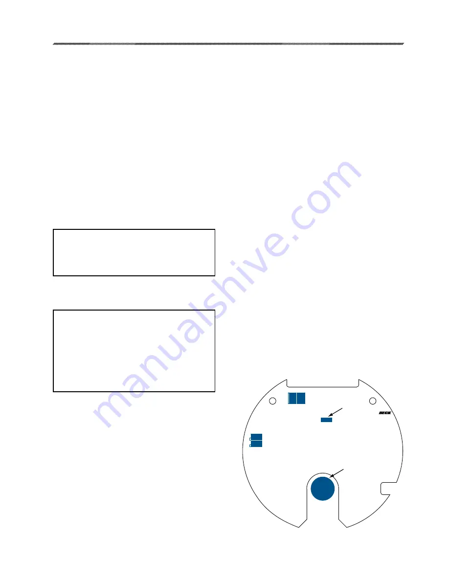
Option 5 Control Board
Figure 6
FEEDBACK
POTENTIOMETER
1
1
CCW
CW
P4
P4
R38
R46
1
J6
J5
J5 / J6
Feedback Signal Calibration, cont'd
15. Position the actuator output shaft to the end
of travel limit that corresponds to 20 mA (i.e.,
to the fully extended position if the actuator
travel is set to extend on an increasing
demand signal, or to the fully retracted
position if the travel is set to retract). Allow
the over-travel limit switch to de-energize the
motor at the limit.
16. Turn trim potentiometer R38 counterclockwise
until the output signal is 20.05 mA ± .001
mA (5 volts on units configured for voltage
output).
17. Repeat steps 15 through 16 until the feedback
signal is calibrated. Adjusting R38 and R46
clockwise increases the signal while counter-
clockwise decreases the signal.
18. Reinstall resistor between terminals 13 and 14
(if used).
NOTE: The input signal is calibrated relative
to the feedback signal. Therefore the shaft
travel limit switches must be properly
adjusted and the feedback signal calibrated
before the input signal can be calibrated.
DEMAND INPUT SIGNAL CALIBRATION
(Option 7 only)
NOTE (Option 7): All actuators are fully
calibrated at the factory and should require
no adjustment; however, if necessary,
calibration may be tested as follows:
Apply 4.00 mA; actuator should position
at 4.00 mA ± .02 mA.
Apply 20.00 mA; actuator should position
at 20.00 mA ± .02 mA.
If adjustments are required, see below.
Input signal calibration is necessary to ensure
that the input signal correctly corresponds to the
position of the actuator output shaft.
Unless otherwise specified at the time of
order, all Group 42 actuators are shipped with the
input signal calibrated for full output shaft travel
and the input signal range set to 4 to 20 milliamps.
A 1 to 5 volt input signal may be specified at time
of order or changed at installation. To convert
a 4 -20 milliamp input configuration to 1-5 volts,
remove input resistor R1 from the terminal board.
To convert a 1-5 volt input configuration to 4-20
milliamps, install a 249 ohm resistor in position
R1. See Figure 5, page 16 for the location of R1.
When properly adjusted, the actuator output
shaft will be in the fully extended position when
the input signal is 20 milliamps (5 volts). At 50%
CALIBRATION


