Beast Tek Dirty Glitch v2.0, Assembly Manual
The Assembly Manual for Beast Tek Dirty Glitch v2.0 is available for free download from manualshive.com. This comprehensive manual provides step-by-step instructions, ensuring an easy and hassle-free assembly process. Get your hands on this essential manual to unlock the full potential of this groundbreaking product.
Share
Download


Reviews:
No comments
Related manuals for Dirty Glitch v2.0

HFS6801+
Brand: Harris Pages: 72

KATOWICE
Brand: Xaoc Devices Pages: 6

CASPER SOFTPOP SP2
Brand: Bastl Pages: 8
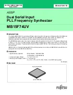
MB15F74UV
Brand: Fujitsu Pages: 25

MB15C02
Brand: Fujitsu Pages: 28

Phaser BI-TRON
Brand: Arturia Pages: 38

MatrixBrute
Brand: Arturia Pages: 21

Viscount Legend Exp
Brand: Key B Organ Pages: 126

EURO STAGE ES30
Brand: Elby Designs Pages: 3

MIDI Bass
Brand: 360 Systems Pages: 6

S-80
Brand: Yamaha Pages: 40

SY-300
Brand: Boss Pages: 12

VP1
Brand: Yamaha Pages: 179

DX7II-FD/D
Brand: Yamaha Pages: 111

SY99
Brand: Yamaha Pages: 156

SumDif
Brand: Shakmat Pages: 3

Mod Medusa
Brand: Shakmat Pages: 15

Rayblaster
Brand: Tone2 Pages: 54


