


5-11
MEGA3 NFPA Medical Gas Notification System
4107 9016 59.03
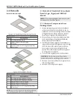
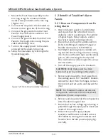
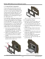
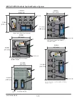
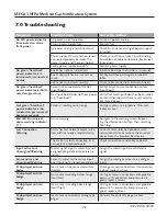
5.3.6 Install Trim Components
The standard retrofit alarm kit comes with
a 20” x 16” trim plate assembly which will
work for most of the typical installations (Fig-
ure 135). In some cases the trim plate is not
needed and the existing rough-in box / wall
opening can be covered by using the trim
ring alone; in that case, remove the 20” x 16”
trim plate prior to installing the trim ring to
the wall/rough-in box.
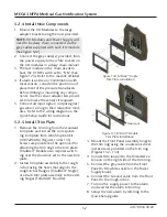
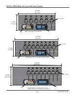
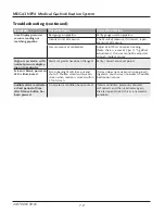
For retrofitting of larger 8-gas rough-in panels
(up to 24” wide), an optional trim plate kit
is required (4107220615) to cover the larger
wall opening (Figure 136). If this is required,
remove the 20” x 16” trim plate from the trim
ring and install the 27” x 16” trim plate prior
to installing the trim assembly to the wall/
rough-in box. *Note the orientation of the
square notches on the trim ring and plate.
1. Position the trim plate over the rough-
in box and determine the best mount-
ing method for your case. Use a level to
check that the trim plate is plumb.
2. Mark the mounting locations on the dry-
wall using the trim plate as your guide.
3. Install the drywall anchors provided as
needed.
4. Reposition the trim plate and install the
screws provided into the anchors and/or
directly into the rough-in box.
Figure 136: Optional Retrofit Area Trim Panel
Figure 135: Standard Trim Plate Assembly
Trim Plate
Trim Ring
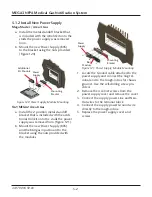
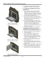
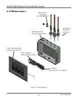
5.3.7 Install Front Panel
1. Mount the Front Panel assembly to the
trim ring using the countersink sheet
metal screws provided on the trim ring.
2. Connect the lanyard to the threaded
extension on the right side of the trim ring
(Figure 137).
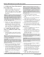
3. Connect the grey cable from the Front
Panel to the white socket on the Power
Supply board.
4. Connect the Ground cable on the Front
panel to the rough-in box using the pro-
vided self-drilling screw.
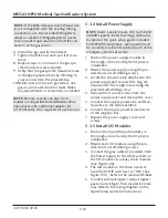
5. Turn on the supply power to the alarm
and wait for the alarm to boot up.
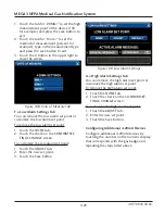
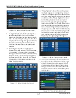
6. Setup the new alarm by referring to the
Quick Setup guide.
Figure 137: Front Panel Installation