


2-6
MEGA3 NFPA Medical Gas Notification System
4107 9016 59.03
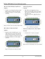
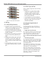
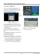
2.3.6 B1X Signal Board
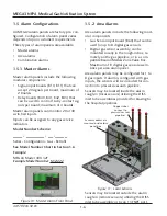
A Master or Combination alarm panel can
contain multiple signal input boards; up to a
maximum of 2 boards or 40 signal inputs.
B10 and B11boards are labeled X01 thru
X20.
Identify each twisted pair of field installed
signal input signal wires inside the alarm
rough-in box.
Route each pair of signal input signal wires as
shown in Figure 24 to appropriate terminals
on input board(s).
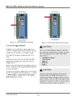
Connect each pair of signal wires to terminal
blocks noting the correct polarity (+,-). Refer
to
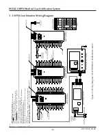
NFPA Master/Combination Wiring Dia-
gram (Section 3.1/3.3)
.
CAUTION
:
Source equipment signal wires must be
connected to normally-closed, dry con-
tacts. No electrical voltage can be present
and contacts must be closed during normal
equipment operation. When contacts open,
an alarm condition will be activated.
CAUTION
:
Do not connect MEGA3 master/combina-
tion alarm to switch/relay contacts connect-
ed to any alarm panels other than those
listed below:
• TotalAlert Infinity
™
• TotalAlert2
• MEGA3
• MEGA2
• MEGA
Figure 24: B1X Signal Board Wire Routing
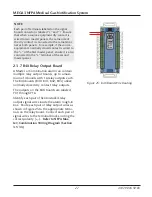
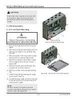
Figure 23: B60 Board Wire Routing