BeaconMedaes 8102371401 Operation And Maintenance Instructions Download Page 31

31

Medical Gas Central Alarm - Medipoint 125 Digital Alarm

4233500107.03

5.2 

Additional Technical Functions.

The  following  section  details  instructions  for  technical 

staff  for  additional  diagnostics.    Figure  41  details  the 

technical interface accessed from the touch screen.

Figure  41  -  Example,  6  gas  setup.  Additional 

technical functions.

Touch Screen - Functional Icons:

Icon

Description

Info

Press - Go to Info screen.

Logs

Press - Go to logs screen.  Password 

controlled (Factory default “1234”.

Settings

Press - Go to setup menus.  Password 

controlled.  See section 3.

5.2.1  Information Screen.

The  information  screen  can  be  accessed  to  view  the 

device software version.  See figure 42.

Press on the Info 

 icon from the main screen to access 

the information screen.

Figure 42 - Information Screen.

Special Characters/Icons:

Icon Description

Exit Icon.

Takes you back to the main screen.

The v#.#.# number indicates the software version.

Note - Figure 42 shows an example only, not the version 

for the supplied device.

Press the exit 

 icon to return back to the main screen.

Note - The system will return back to the main screen 

automatically if a new alarm condition becomes active, 

or after one minute if the alarm is not manually exited 

from the information screen.

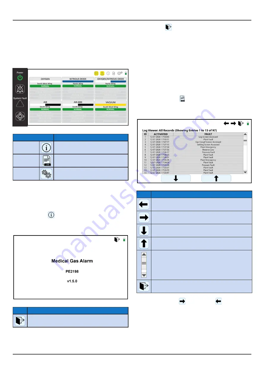
5.2.2  Data Logging Screen.

The  data  logging  screen  can  be  accessed  to  view  the 

history of events for medical gas pipeline pressure faults 

and user access to the settings menus.  See figure 43.

Press  on  the  logs   

  icon  from  the  main  screen  to 

access the data logs.  The first screen shows all entries.

Figure 43 - Data logging Screen, All data entries.

Special Characters/Icons:

Icon Description

Previous Icon.

Takes you to the previous logs screen.

Next Icon.

Takes you to the next logs screen.

Down Icon.

Jumps down 50 records on the current logs screen

Up Icon.

Jumps up 50 page on the current logs screen

Scroll Bar.

Press, hold and drag the scroll bar navigate between 

the selected 50 records.

Exit Icon.

Takes you back to the main screen.

Press  on  the  next 

  or  previous 

  icon  to  cycle 

through  the  alternative  data  logging  screen.    After  the 

main  all  entries  data  screen,  the  next  set  of  screens 

will be filtered by the medical gas service faults, in the 

older of gas input from Column 1 through to Column 6 

depending on the number of gasses setup on the alarm.  

See figure 44 for an example of the filtered by gas fault 

screen.

Summary of Contents for 8102371401

Page 1: ...Operation and Maintenance Instructions Medical Gas Central Alarm Medipoint 125 Digital Alarm Part number 4233500107 Revision 03 Jan 2021...

Page 2: ...hone 44 0 1246 474242 Email gbn info beaconmedaes com Website Contacts www beaconmedaes com BeaconMed s reserves the right to make changes and improvements to update products sold previously without n...

Page 3: ...in screen 3 6 Exit Setup Screen 3 7 Confi guration Menu Map 4 0 Commissioning 4 1 Alarm panel test 4 2 Checking the slave relay output 4 3 Checking the remote audible warning 4 4 Medical gas alarm fau...

Page 4: ...ckaged and stored in controlled conditions Environmental Operating Conditions Adverse environmental conditions and harsh abrasives or chemicals may cause damage to the unit Environmental Protection Di...

Page 5: ...rammed from on screen menus to provide a fully flexible alarm system Allowing the panels to be adapted to suit any hospital s medical gas monitoring requirements see section 1 12 for programming detai...

Page 6: ...nt of any defect within the monitored functions the SYSTEM ALARM LED illuminates flashing accompanied by the audible warning and the defective gas service alarm display status bar illuminates An inter...

Page 7: ...operty and shall not without our permission be altered ATLAS COPCO STANDARD Class Tolerances if not indicated according to Material Treatment Name Scale Family Drawing owner Secrecy Class 1102 K Compa...

Page 8: ...p to four fault conditions yellow or red flashing alarm conditions to show the gas service status All alarm conditions are illuminated by a flashing display and accompanied by an audible warning Each...

Page 9: ...on these PCB s which are interconnected by means of a multi way ribbon cable and polarised connector see figure 2 3 The area central alarm internal electrical installation complies with all relevant...

Page 10: ...cular displayed alarm condition only This facility is designed for use when the plant or pipeline is shut off for a prolonged period On returning the pipeline pressure to NORMAL this feature automatic...

Page 11: ...nnections have 5 terminals each See table 2 for details for standard options Each gas service and fault legend is also fully customisable through the on screen setup menus TABLE 2 GAS SERVICE CONNECTI...

Page 12: ...uired by the contract specification Feed cables into the box leaving 400mm to 75 150 105 105 7 260 5 TOP 40 40 40 40 17 20 KNOCKOUT SEGMENTS 200 17 45 2 0 KNOCKOUT SEGMENTS BACKBOX SURFACE Figure 10 B...

Page 13: ...Power supply PCB installation No Description QTY 1 Back Box 1st fix supply N A 2 Power supply PCB 2nd fix supplied loose 1 3 PCB Spacer 2nd fix supplied loose 4 4 M3 Nut 2nd fix supplied loose 4 5 M3...

Page 14: ...nections No Description QTY 1 Earth cable 2nd fix supplied assembled 1 2 M3xNut 2nd fix supplied loose 4 3 M3 washer 2nd fix supplied loose 4 Typical earth stud assembly 2 2 3 1 Alarm Door Earth Stud...

Page 15: ...igure 15 Alarm data connection MP125D 1 S1 ON IN OUT A B A B S MP125D 2 S1 OFF IN OUT A B A B S MP125D 3 S1 ON IN OUT A B A B S Note S terminal is for connecting the screen cable 2 2 6 Remote audible...

Page 16: ...mmissionedimmediately disconnect the standby battery Connect electrical power supply wires to electrical power supply plug terminals E N and L 1 2 Figure 21 Alarm door security fastener No Description...

Page 17: ...aracters Icons Icon Description Enter Key TAB key Moves to next field and highlights text Highlighted text will be overwritten on next key press Tick key Apply update and takes you to the main screen...

Page 18: ...e Alarm setup 2 screen or press the Exit Icon to go back to the main operating screen 3 4 Alarm Setup Screen 1 Figure 26 The following steps describes the setup process for the alarm setup screen 1 3...

Page 19: ...e new numerical password Press the TAB key or press the next field to go to the next field Confirm Use the num pad to enter the password again Press the ENTER key or press anywhere on the screen away...

Page 20: ...setup process for the main gas service setup screen Figure 27 Main Gas Service Setup screen Special Characters Icons Icon Description Previous Icon Takes you to the previous menus screen Next Icon Tak...

Page 21: ...k to set as inputs tick to set as remote transmission Press to toggle between the options 3 5 6 Location Special Characters Icons Description Exit Icon Takes you back to the main screen O2 Oxygen Gas...

Page 22: ...elds will be editable 3 5 7 1 Standard gas options These fields allow for selecting the source equipment type available for the standard gas type selected Press on the matching equipment type to auto...

Page 23: ...etup screen Figure 33 Main Gas Service Setup screen Special Characters Icons Icon Description Previous Icon Takes you to the previous menus screen Next Icon Takes you to the next menus screen Exit Ico...

Page 24: ...key press Previous Icon Takes you to the previous menus screen Next Icon Takes you to the next menus screen Exit Icon Takes you back to the main screen Reject Icon Rejects changes Accept Icon Accepts...

Page 25: ...6 shows examples of all status flashing See table 6 in section 5 Operation of the Medipoint 125 Digital alarm for troubleshooting Figure 36 Alarm Test Button example 6 gas 4 2 Checking the slave relay...

Page 26: ...e table 2 section 1 8 for full list of standard gas service fault legends Check that the MUTE switch operates satisfactorily Press the audible alarm will be silenced and the mute icon will show on scr...

Page 27: ...ED is flashing red The audible alarm is active See figure 39 fro example Figure 39 Example Gas service 1 connection fault 4 5 3 Input Reconnect Reconnect the input plug to gas channel System will retu...

Page 28: ...d and the alarm condition remains the audible warning will re sound after 15 mins and a further MUTE selection will be required Should a further alarm condition occur after the panel has indicated a f...

Page 29: ...mple shows gas service fault 4 Power LED Green On System Fault Black Off Gas Status Bar Red Flashing Audible Active Audible Mute Gas service fault flashing Mute activated Audible Silenced for 15 minut...

Page 30: ...lank normal Yellow flashing fault Fault status 3 Blank Fault status 4 Blank normal Red flashing fault Manifold Control Systems Normal status Green normal blank during fault Fault status 1 Blank normal...

Page 31: ...to the main screen automatically if a new alarm condition becomes active or after one minute if the alarm is not manually exited from the information screen 5 2 2 Data Logging Screen The data logging...

Page 32: ...s distributors will be able to supply similar contracts in other areas CAUTION It is essential that only genuine BeaconMed ssparepartsarefittedduringmaintenance WARNING Obtain a work permit or equival...

Page 33: ...33 Medical Gas Central Alarm Medipoint 125 Digital Alarm 4233500107 03 Figure 45a Alarm panel assembly details...

Page 34: ...34 Medical Gas Central Alarm Medipoint 125 Digital Alarm 4233500107 03 Figure 45b Alarm panel assembly details...

Page 35: ...e 5 year maintenance replace the LCD screen and backup butteries See maintenance procedures in 6 1 and figures 45a 45b for details 8 RECOMMENDED SPARES Table 8 details the list of recommended spares t...

Page 36: ...2460 Atlas Copco Medical Ltd Telford Crescent Staveley Derbyshire S43 3PF UK Tel 44 0 1246 474242 www beaconmedaes com Atlas Copco Airpower n v Boomsesteenweg 957 2610 Wilrijk Belgium...

Reviews: