


5
1
2
3
4
5
1
2
10 cm
45°
+
-
+
-
45°
E
R
L
A
U
B
T
Z
E
R
T I
F I Z
I E R U N G
N
A
C
H
EN 1
600
5
E
N
A
B L E
S
A C C
O R
D
A
N
C
E
W
I
T
H
E
R
L
A
U
B
T
Z
E
R
T I
F I Z
I E R U N G
N
A
C
H
DIN 1
865
0
E
N
A
B L E
S
A C C
O R
D
A
N
C
E
W
I
T
H
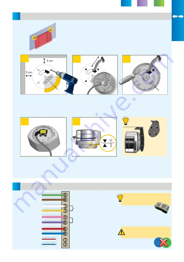
Door control without test:
connect red and blue wires to
power supply (no polarity)
Use the mounting template to
position the sensor correctly. The
grey area indicates the detection
range. Drill 4 holes and make a
hole for the cable if possible.
Pass the cable +/- 10 cm though
the cable opening. If drilling an
opening is not possible, use the
cable conduits on the back side
of the bracket.
Position the bracket and fasten
the 4 screws firmly in order to
avoid vibrations.
Position the housing on the
bracket and turn the sensor until
the two triangles are face to face.
MOUNTING
WIRING
POWER
POWER SUPPLY -
RELAY 1 - OPENING
VIA VIRTUAL PUSH BUTTON
RELAY 2 - SAFETY
TEST +
TEST -
NOT USED
GREEN
BROWN
WHITE
YELLOW
PINK
VIOLET
RED
BLUE
WHITE/RED
WHITE/BLUE
Open the protection cover, plug
the connector and position the
cable in the slit.
Close the protection cover and
fasten it firmly.
Use the Power Supply Module
(24V DC, 0.75 A) if needed.
Use the LBA accessory if needed.
On sliding doors, the LZR should be installed
on one of the two door frame corners.
LZ
R
-P
11
0 O
N S
LI
D
IN
G D
O
O
R
S
Please go to the section that fits your door application:
SLIDING
SWINGING
REVOLVING
P. 5
P. 9
P. 13