OFT10W-3455J User’s Manual
20
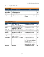
• 2.3.4.3 Internal Headers
Label
Function
Note
Page
DCIN_PWR
4-Pin Power Connector
1 x 4 shroud header, 2.54mm
9V~36V, 6A Max
(19V recommended)
27
F_PANEL
System Panel Connector
2 x 5 header, pitch 2.54mm
28
SYS_FAN
System Fan Connector
1 x 4 wafer, Pitch 2.54mm
28
SATA3
Serial ATA 3.0 Connector
7-pin header
29
SATA_PWR
SATA Power Connector
29
F_USB1
USB2.0 Port 1
2 x 5 box header, pitch 2.54mm
31
F_USB2
USB2.0 Port 2
2 x 5 box header, pitch 2.54mm
(“F_USB2” header port 0 (the
USB set on pin 2, 4, 6, 8, 10 only)
Supports Dual Role (OTG) when
BIOS “XDCI Support” is set at
“Device Mode”).
31
COMA
Serial Port A
2 x 5 wafer header, pitch
2.00mm
32
COMB
Serial Port B
2 x 5 wafer header, pitch
2.00mm
32
LVDS
LVDS Panel Connector
2 x 20 header, 1.25mm pitch
wire to board connector (WTB)
Mating Cable Reference:
Cable Housing: Hirose®
“DF13-40DS-1.25C” or eq
Cable Terminal: Hirose®
“DF13-2630SCF” or eq
32
BACKLIGHT
LVDS Panel Backlight Connector 1 x 5 wafer header, pitch
2.00mm
Mating Cable Reference:
Cable Housing: Molex®
“87369-0500 (P=2.0mm)” or eq
Cable Terminal: Molex®
“502128000” or eq
33
I2C
I2C Connector
1 x 3 header, 2.54mm
33
Summary of Contents for OFT10W-3455J
Page 1: ...OFT10W 3455J User s Manual 1 OFT10W 3455J Intel J3455 SoC User s Manual Edition 1 01 Nov 2022...
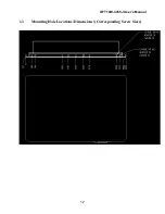
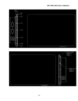
Page 12: ...OFT10W 3455J User s Manual 12 1 3 Mounting Hole Locations Dimensions Corresponding Screw Sizes...
Page 13: ...OFT10W 3455J User s Manual 13...
Page 14: ...OFT10W 3455J User s Manual 14...
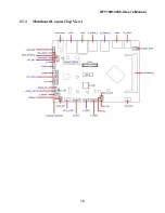
Page 18: ...OFT10W 3455J User s Manual 18 2 3 3 Mainboard Layout Top View...
Page 53: ...OFT10W 3455J User s Manual 53 4 7 14 Hardware Monitor Monitor hardware status...


