35
POWER SUPPLY DIAGNOSTICS
12
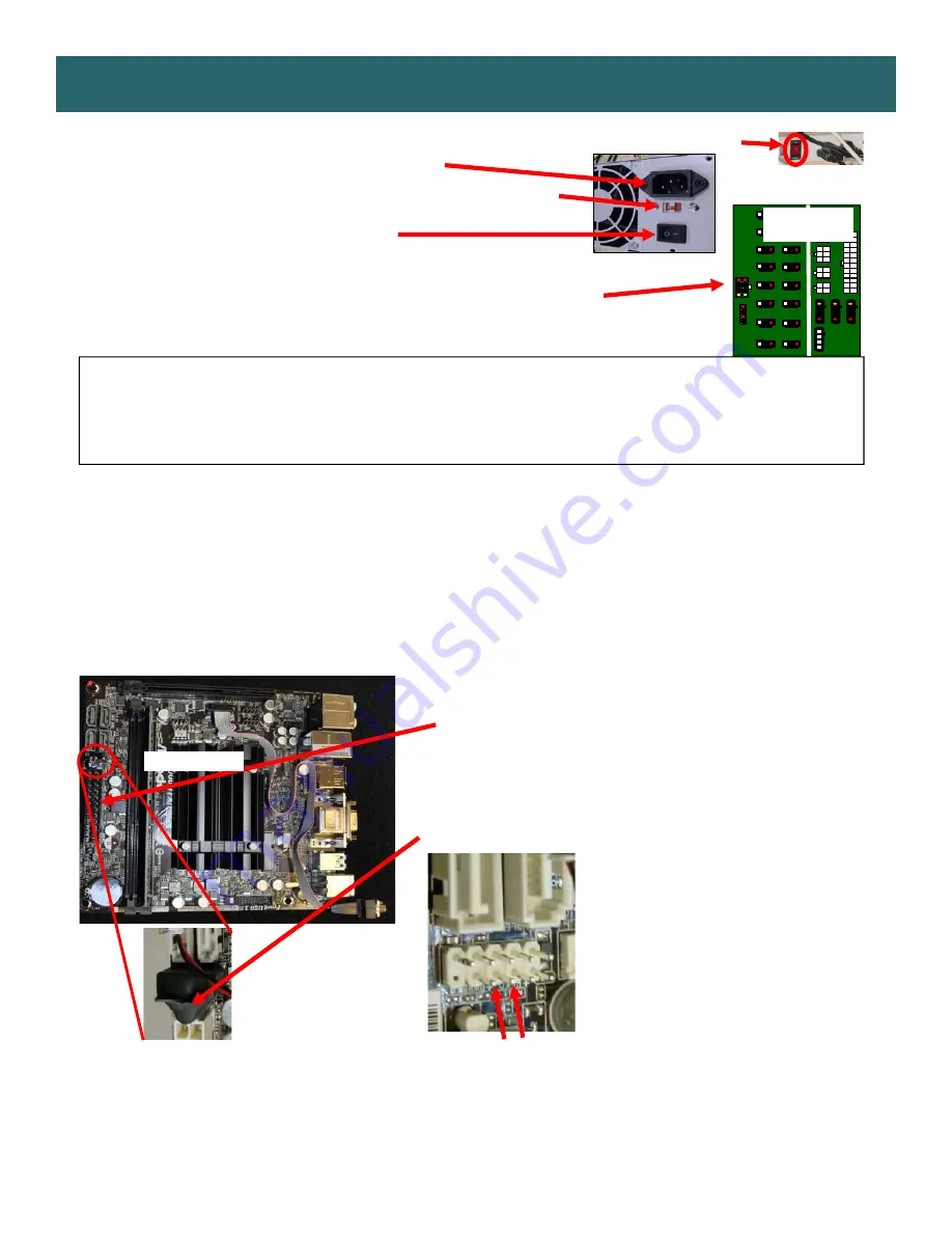
1.) Verify AC power to game. Check power strip in front door. The rocker switch should be illuminated.
2.) Check connection to power supply.
3.) Ensure Power Supply switch is set to 115V (or 230V)
(
Some model power
supplies may not have this)
4.) Ensure Power switch is on.
5.) Ensure fan is turning.
- If power supply fan is turning and there is no 12 Volt out:
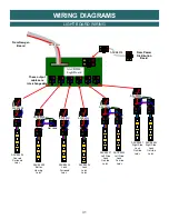
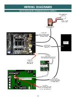
Check power supply cables to the Power Distribution Board.
This board takes the power in, and directs it to the different 12 volt loads.
Replace power supply if this board is not receiving 12 volts. (AAPS1013-PTL)
- If power supply fan is not turning, then continue to “Verify Power to Motherboard”
Verify Power to Motherboard
The motherboard will turn on power supply.
If your game has no 12 volts, it may be the motherboard not turning on.
Also - there may be a 12 volt short somewhere in cabinet that is not allowing the power supply to turn on.
Minimize load on power supply and isolate short
Unplug the power supply cables going to the Power Distribution Board.
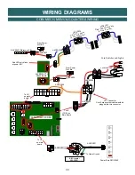
This will leave the power supply, motherboard, and monitor left plugged in together.
If power supply, motherboard, and monitor now turn on:
Plug in the Power Distribution Board to power supply, but unplug all of the outputs from the board.
Turn on game and verify the 12 volts is good.
Then plug in one component at a time to power supply to locate short.
If power supply still does not power on, then continue to steps 1,2, and 3.
If power supply still does not power on, replace power supply (AAPS1013-PTL),
or replace motherboard. (AAMB9-SHD)
3
- Motherboard “Jump Start”
As a last resort, you may start motherboard by
quickly touching these 2 pins at the same
time, then quickly release
Motherboard may turn ON and boot normally.
1
- Check single connection from power supply.
AAMB9A-SHD
2
- Verify these pins are covered by connector with a single capacitor.
If the connector is missing, continue to step 3 to jump the pins
under this connector.
AACB5156
Power Dist. Bd
Summary of Contents for Pop the Lock
Page 12: ...12 HEIGHT MODIFICATION OPTIONS...
Page 23: ...23 MAINBOARD PINOUT 15...
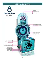
Page 39: ...39 DECALS DIAGRAM 20...


