background image


Installing and Maintaining the HRPSU

2-10


114312 Rev. C


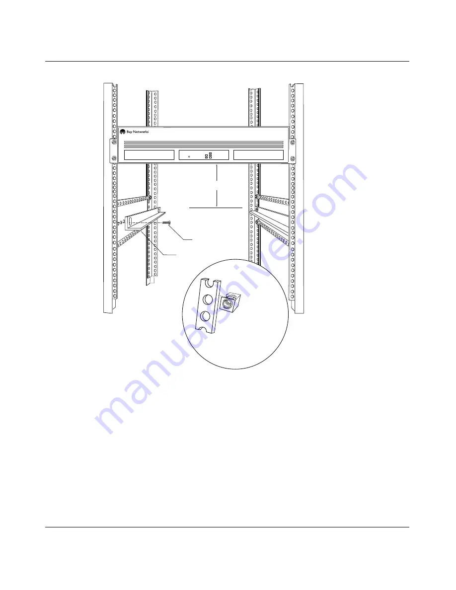
Figure 2-7.

Attaching Angle Brackets

  Run 

  Boot

  Diag         

Local Power

 Height:
5.25 in. (13.3 cm) minimum

 Depth
19.5 in. (49.5 cm) minimum

 Bracket
(2 places)

 Screws
(2 places)

Access Stack Node

 If rack rail is
 not threaded,
attach cagenut.  

Rail

Cagenut 

ASN0004A

Remote Power

Summary of Contents for HRPSU

Page 1: ...Part No 114312 Rev C November 1996 Installing and Maintaining the HRPSU ...

Page 2: ...X BLNX EZ Install EZ Internetwork EZ LAN PathMan PhonePlus Quick2Config RouterMan SPEX Bay Networks Bay Networks Press the Bay Networks logo and the SynOptics logo are trademarks of Bay Networks Inc Third Party Trademarks All other trademarks and registered trademarks are the property of their respective owners Statement of Conditions In the interest of improving internal design operational functi...

Page 3: ...ause harmful interference and 2 this device must accept any interference received including interference that may cause undesired operation Operating this equipment in a residential area is likely to interfere with radio communications in which case the user at his her own expense must correct the interference Shielded compliant cables must be used with this unit to ensure compliance with the Clas...

Page 4: ... Council for Interference by Data Processing Equipment and Electronic Office Machines that are aimed at preventing radio interference in commercial and or industrial areas Consequently when this equipment is used in a residential area or in an adjacent area thereto radio interference may be caused to equipment such as radios and TV receivers Compliance with the applicable regulations is dependent ...

Page 5: ...ch it was acquired is inoperative 3 Licensee may make a single copy of the Software but not firmware for safekeeping archives or backup purposes 4 Licensee may modify Software but not firmware or combine it with other software subject to the provision that those portions of the resulting software which incorporate Software are subject to the restrictions of this license Licensee shall not make the...

Page 6: ... install the Site Manager product as specified in the Documentation This right is granted solely as necessary for use of Site Manager on hardware installed with licensee s network 11 This license will automatically terminate upon improper handling of Software such as by disclosure or Bay Networks may terminate this license by written notice to licensee if licensee fails to comply with any of the m...

Page 7: ...standalone unit that can support up to four network devices equipped with redundant power supply outlets The HRPSU is a modular system consisting of a power rack Order No AA0002001 with slots for four power supply modules Order No AA0005003 You can install as many modules as needed between one and four in the power rack Figure 1 1 shows an HRPSU with all four power supply modules installed Figure ...

Page 8: ...perational Figure 1 2 shows the front of the HRPSU with the front panels removed from two slots and a power supply module The blank front panel on each power supply slot normally remains on the HRPSU until a module is installed The power supply module which has a permanent front panel is provided with a latch for handling the module and for keeping it in place during operation Figure 1 2 HRPSU Pow...

Page 9: ...oor in locked position The open slot on the left shows the power supply connector on the backplane When you insert a power supply module into the slot the flange on the rear of the module releases the safety door allowing the module to connect to the backplane The module s power switch located on the front panel is recessed deeply to prevent you from accidentally turning off the module Figure 1 3 ...

Page 10: ...e of the HRPSU no other setup is required The HRPSU power switch turns off all power to the unit The AC power cord plugs into a wall outlet This allows the network device to have an AC power source separate from the HRPSU The HRPSU requires a dedicated 15 A branch circuit for 120 V AC power service North American and Japanese users need to use the Bay Networks 15 A power cords for their countries ...

Page 11: ...eview the installation procedures in Chapter 2 Read all safety sheets included with the shipment and the caution and warning labels on the unit Observe all safety precautions A Phillips screwdriver is required for some installation procedures ...

Page 12: ......

Page 13: ...ng Options There are three options for cabling a network device to an HRPSU power supply module Table 2 1 explains the options and indicates the figure that illustrates each one Depending on your network device you will use 24 pin cables or 16 pin cables with an adapter Refer to the figure for the cabling option that applies to your device Table 2 1 Options for Cabling a Network Device To Connect ...

Page 14: ... with end to end screws attaches to the network device the end with offset screws attaches to the HRPSU An EMI gasket is supplied with the cable see figure You place the gasket over the connector on the power supply module before you plug in the cable Figure 2 1 Cabling with One 24 Pin Cable HRP0011A 1 2 3 4 CONSOLE XMT RCV 1 2 3 DCD SD SD S P TX B Y P A S S PHY B PHY A F FDDI MM 34003 2 ETHERNET ...

Page 15: ...ure 2 2 shows an adapter The adapter has two 16 pin connections labeled P1 and P2 Network devices that require the use of two 16 pin cables attach to both connections on the adapter P1 and P2 devices using a single 16 pin cable attach to the bottom P1 connection Figure 2 2 Adapter for 16 Pin Cable Connections 1 2 16 pin Connector Adapter Adapter standoff P 1 P 2 Captive screw P 1 P 2 ...

Page 16: ...rmly press the 16 pin adapter connector into the HRPSU 24 pin connector 2 Insert and tighten the captive screw supplied for the adapter Note By default the adapter for 16 pin cable connections is shipped with a protective cover over the P2 connection If your network device requires two 16 pin connections you must remove this cover before attempting to attach the second network device cable Note If...

Page 17: ...e 2 3 Cabling with One 16 Pin Cable Using Two 16 Pin Cables Figure 2 4 shows the cabling between two 16 pin redundant power connectors on a network device and an HRPSU power supply module using an adapter This type of connection provides up to 210 W Note When using a single 16 pin cable plug the cable into the lower connector on the adapter P1 UL UL 100 240 1 2A 50 60Hz Console Modem Redundant Pow...

Page 18: ...s the length of cabling necessary to attach the device You mount the HRPSU before installing the power supply modules Once it is in place you install all of your power supply modules then attach the cables to the network device s and the HRPSU Mounting the HRPSU on a Surface The HRPSU does not require any preparation or tools for mounting on a solid surface Sturdy non slip feet are built into the ...

Page 19: ...ices place the unit on a surface that will support the power supply and the network devices you intend to attach to it refer to Appendix A for the weight of the HRPSU power rack and modules Set the network device s on the HRPSU HRP0005A Non Slip feet RUN BOOT POWER Access Stack Node RUN BOOT POWER Access Stack Node ...

Page 20: ... Appendix A When you have the required equipment to install the HRPSU in a rack 1 Measure at least 5 25 in 13 3 cm of free vertical space inside the rack If you plan to stack the HRPSU with ASNs multiply 5 25 in by the number of nodes in the stack Then make sure the rack has enough contiguous free vertical space for the stack 2 Locate the nearest two rail holes below the area you just measured tha...

Page 21: ...rack has horizontal bracket supports align the angle brackets with the supports Otherwise brace the angle brackets between the side rails c Insert a 10 32 screw through the slots at each end of the bracket and into the holes in the rack supports Do not tighten the screws d Adjust each bracket vertically along the bracket slots until the bracket is 0 78 in 1 98 cm below the center of one hole in th...

Page 22: ...C Figure 2 7 Attaching Angle Brackets Run Boot Diag Local Power Height 5 25 in 13 3 cm minimum Depth 19 5 in 49 5 cm minimum Bracket 2 places Screws 2 places Access Stack Node If rack rail is not threaded attach cagenut Rail Cagenut ASN0004A Remote Power ...

Page 23: ...he HRPSU is to be mounted to double posts flush mounted as in Figure 2 8 reverse the brackets as shown on the right in Figure 2 8 The front of the HRPSU will be flush with the rack mounted network devices Figure 2 8 Attaching Flanges to the ASN 5 Place the HRPSU on the angle brackets in the rack Align the flange holes with the holes in the front vertical supports on the rack Figure 2 9 If the rack...

Page 24: ...losure Rack 6 Insert a 10 32 screw through each flange hole and into the corresponding holes in the front vertical supports of the rack 7 Tighten the screws with a Phillips screwdriver Cage Nut screw 4 places Rail without threaded holes use Cage Nut HRP0007A RUN BOOT DIAG POWER Access Stack Node ...

Page 25: ... Rack Install the power supply module using the following steps 1 From any slot remove the blank front panel as follows with your fingers under the top edge of the panel pull outward Discard the panel 2 Lift the latch of the power supply module and slide the module straight into the slot between the side rails The flange on the back of the module releases the safety door as the module pushes the d...

Page 26: ...e HRPSU 2 Tighten the captive screws 3 If you are using a 24 pin cable place an EMI gasket over the connector see Figure 2 1 before attaching a cable to the HRPSU 4 Plug the cable s into the HRPSU and tighten the captive screws 5 When all cables are plugged in plug the HRPSU AC power cord into the HRPSU and into a wall outlet 6 Turn on the power switch on the back of the HRPSU power rack 7 Turn on...

Page 27: ...the AC power switch on the rear of the HRPSU is ON 3 Make sure that all connections are tight 4 Turn off the power supply modules power switch and turn it on again to reset the power supply module Table 2 2 Status Indicators LED Color Meaning HRPSU Module Power OK Green Dark The HRPSU is capable of sending power to the network device if needed The HRPSU is not connected to the network device Netwo...

Page 28: ......

Page 29: ... 1 Turn off the power supply switch on the front of the HRPSU module to be replaced 2 Lift the latch on the front of the module and using it as a handle pull the module straight out of the slot When the module is removed the safety door falls shut and locks into place 3 Lift the latch of the new power supply module and slide the module straight into the slot between the side rails The flange on th...

Page 30: ...on the power supply module s switch and verify that the green Power OK LED is lighted Figure 3 1 Removing Power Supply Module from HRPSU Power Rack Redunant AC Power Module Power OK HRP0004A Latch Redunant AC Power Module Power OK RUN BOOT POWER Access Stack Node ...

Page 31: ...8 kg Power Supply Module Weight 5 15 lb 2 34 kg Table A 2 Environmental Requirements Operating temperature 10 to 40 C Cooling 12 V DC ball bearing fan inside each power supply module Table A 3 Wall Receptacle Requirements Country Receptacle Voltage North America and Japan National Electrical Manufacturers Association NEMA 10 A 200 240 V 15 A 100 120 V Any other country Standard wall receptacle 200...

Page 32: ...l Line frequency 47 to 63 Hz Voltage amperes rating 1200 VA Input power 1150 W Input voltage 100 to 240 V Input current rating 12 7 A Output voltages 5 V 40 A 12 V 4 5 A 12 V 0 5 A Safety agencies UL listed Certified to CSA standards TUV licensed Thermal rating 4000 BTU maximum fully powered chassis ...

Page 33: ...ome page on the World Wide Web The Bay Networks URL is http www baynetworks com For information about your particular network device refer to the manual that was supplied with it Ordering Bay Networks Publications To purchase additional copies of this document or other Bay Networks publications order by part number from the Bay Networks Press at the following telephone or fax numbers Telephone U S...

Page 34: ......

Page 35: ...ections 2 3 Figure 2 3 Cabling with One 16 Pin Cable 2 5 Figure 2 4 Cabling with Two 16 Pin Cables 2 6 Figure 2 5 HRPSU Mounted on a Surface 2 7 Figure 2 6 Locating the Rail Holes 2 9 Figure 2 7 Attaching Angle Brackest 2 10 Figure 2 8 Attaching Flanges to the HRPSU 2 11 Figure 2 9 Mounting the HRPSU in an Enclosure Rack 2 12 Figure 2 10 Inserting Power Supply Module in HRPSU Power Rack 2 13 Figur...

Page 36: ......

Page 37: ...Options for Cabling a Network Device 2 1 Table 2 2 Status Indicators 2 15 Table A 1 Physical Specifications A 1 Table A 2 Environmental Requirements A 1 Table A 3 Wall Receptacle Requirements A 1 Table A 4 Electrical Specifications A 2 ...

Page 38: ......

Page 39: ...ervice FTP xvii Support Source CD xviii CompuServe xviii InfoFACTS xix How to Get Help xix Chapter 1 Overview of the HRPSU Introduction to the HRPSU 1 1 Preparing for Installation 1 4 Chapter 2 Installing the HRPSU Cabling Options 2 1 Using One 24 Pin Cable 2 2 Installing an Adapter for 16 Pin Cables 2 3 Using One 16 Pin Cable 2 4 Using Two 16 Pin Cables 2 5 Mounting the HRPSU 2 6 Mounting the HRP...

Page 40: ...ly Module in the HRPSU Power Rack 2 13 Connecting Cables and Switching on Power 2 14 If the Power Module Doesn t Turn On 2 15 Chapter 3 Maintaining the HRPSU Replacing a Power Supply Module in the HRPSU 3 1 Appendix A Technical Specifications ...

Page 41: ...enters are connected via a redundant Frame Relay Network to a Common Problem Resolution system enabling them to transmit and share information and to provide live around the clock support 365 days a year Bay Networks Information Services complement the Bay Networks Service program portfolio by giving customers and partners access to the most current technical and support information through a choi...

Page 42: ...Our complete range of contract and noncontract services also includes equipment staging and integration installation support on site services and replacement parts delivery within approximately 4 hours To purchase any of the Bay Networks support programs or if you have questions on program features use the following numbers In addition you can receive information on support programs from your loca...

Page 43: ... can View a listing of support cases and determine the current status of any open case Case history data includes severity designation and telephone e mail or other logs associated with the case Customize the listing of cases according to a variety of criteria including date severity status and case ID Log notes to existing open cases Create new cases for rapid efficient handling of noncritical ne...

Page 44: ...ices maintain an active forum on CompuServe a global bulletin board system This forum provides file services technology conferences and a message section to get assistance from other users The message section is monitored by Bay Networks engineers who provide assistance wherever possible Customers and resellers holding Bay Networks service contracts also have access to special libraries for advanc...

Page 45: ... Canada call toll free 1 800 786 3228 Outside North America toll calls can be made to 1 408 764 1002 In Europe toll free numbers are also available for contacting both InfoFACTS and CompuServe Please check our Web page for the listing in your country How to Get Help Use the following numbers to reach your Bay Networks Technical Response Center Technical Response Center Telephone Number Fax Number ...

Page 46: ......

Reviews: