11
INSTRUCTIONS FOR THE INSTALLER
010828_0200
C
33
C
33
C
13
C
13
C
43
C
53
C
83
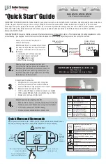
Figure 8
Figure 7a
0301_1007
18
17
16
19
PRIME HT 240 - HT 280 - HT 330
Figure 7b
0301_1008
18
17
16
19
PRIME HT 1.120 - HT 1.240 - HT 1.280
• template
• gas cock (16)
• inlet water tap with filter (17)
• heating system delivery cock (19)
• heating system return cock (18)
• seals
• telescopic joints
• 8 mm wall plugs and hooks
We guarantee ease and flexibility of installation for a gas-fired forced draft boiler thanks to the fittings and fixtures sup-
plied (described below).
The boiler is especially designed for connection to an exhaust flue / air ducting, with either coaxial, vertical or horizontal
terminal. By means of a splitting kit a two-pipe system may also be installed.
In case exhaust and intake flues not supplied by BAXI S.p.A. have been installed, these must be certified for the
type of use and must have a maximum pressure drop of 100 Pa.
Warnings for the following types of installation:
C
13
, C
33
The terminals for the split flue must be provided for within a square with 50
cm sides. Detailed instructions are given together with each accessory.
C
53
The terminals for combustion air intake and for the expulsion of combu-
stion products must not be provided for on opposite walls of the building.
C
63
The maximum pressure drop of the ducts must not exceed 100 Pa. The
ducts must be certified for the specific use and for a temperature of over
100°C. The chimney flue must be certified in accordance with the prEN
1856-1 Regulation.
C
43
, C
83
The chimney or flue used must be suitable for the use.
14. INSTALLATION OF FLUE AND AIR DUCTS
13. FITTINGS PRESENT IN THE PACKAGING