background image

4. 

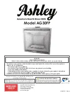
The smoke match should be placed horizontally into the convection box at the right

hand side. There is a notch in the black cross member. Insert the tube so that the neck of
its flared end is 5mm passed and in contact the cross member (See figure 45).
The installation is satisfactory if the
smoke is drawn into the appliance.
If the smoke is not drawn into the
appliance leave the appliance alight at the
maximum setting for a further ten
minutes and then repeat the test. If the
smoke is still not drawn into the
appliance inspect the sealing to the
fireplace surround. If the sealing is
satisfactory but the appliance is installed
with the flue restrictor (See section 8
point 9) remove the restrictor, reseal the
appliance and retest. If smoke is still not
drawn into the appliance 

disconnect the

appliance and seek expert advice.

5.

If the above test is satisfactory open all internal connecting doors, hatches, etc. in the

room. Keep all doors and windows that open to the outside of the building closed.
Recheck for spillage as above. If an extractor fan is installed in the same room as the
appliance or a connecting room, check that spillage does not occur with the fan
operating and all doors and other openings between the fan and the appliance open.
If the smoke is drawn into the appliance, continue with the installation. If the test is not
satisfactory 

disconnect the appliance and advise the customer of the cause of

failure

.

15.3 Flame supervision and spillage monitoring system.

This pilot unit includes a system that will automatically shut off the gas supply if the
pilot flame goes out or if there is insufficient oxygen due to spillage or poor ventilation.
Check that the system operates properly as follows;

1.

Light the appliance. Set the slide control to the maximum burning position and leave

for one minute.

2. 

Set the control to the ‘Low’ burning position. Isolate the gas supply at the inlet ‘T’

connector. The pilot and main burner will go out. 

Note the time when the pilot goes

out

Listen for a snap sound at the gas tap. 

Note the time when the sound is heard

.

This sound is caused by an electromagnetic valve shutting off the gas supply through
the tap. The valve is located in the body of the tap. The valve should operate 

within 60

seconds of the pilot going out

If the valve does not operate within this time limit do

not allow the appliance to be used until the fault has been corrected.

This monitoring system must not be adjusted, bypassed or put out of operation.

Page 37

INSTALLER GUIDE

© 

Baxi Heating U.K. Limited 2007.

Figure 45. Smoke match tube position
(Shown with ‘Visage’ fascia)

Summary of Contents for 740FS

Page 1: ...ctorily However if further information is required our Baxi Fires Division Technical Helpline will be pleased to help Telephone 08706 061 065 National call rates apply in the United Kingdom In the Republic of Ireland Telephone 0044 8706 061 065 THIS APPLIANCE IS FOR USE WITH NATURAL GAS G20 WHEN CONVERTED USING CONVERSION KIT NO 0595211 THIS APPLIANCE IS FOR USE WITH PROPANE GAS G31 THIS APPLIANCE...

Page 2: ...mission to reproduce any part of this publication should be made giving details of the proposed use to the following address The Company Secretary Baxi Heating UK Limited Pentagon House Sir Frank Whittle Road Derby DE21 4XA Warning Any person who does any unauthorised act in relation to a copyright work may be liable to criminal prosecution and civil claims for damages Baxi Fires Division Erdingto...

Page 3: ...ity system accepted by the British Standards Institute The Highest Standards Baxi Fires Division is a member of the Society of British Gas Industries which works to ensure high standards of safety quality and performance Careful Installation Baxi Fires Division is a CORGI registered company All our gas fires must be installed by a competent CORGI Registered Installer in accordance with our Install...

Page 4: ...r spillage 36 15 3 Flame supervision and spillage monitoring system 37 16 FINAL REVIEW 38 17 SERVICING PARTS REPLACEMENT 39 17 1 Checking the aeration setting of the burner 40 17 2 To remove the ignition microswitch 40 17 3 To remove the gas shut off microswitch 40 17 4 To remove the fascia 41 17 5 To replace the control slide unit 42 17 6 To replace the control slide button 43 17 7 To remove the ...

Page 5: ...t to lift the fire If for any reason this weight is considered too heavy then obtain assistance When lifting always keep your back straight Bend your legs and not your back Avoid twisting at the waist It is better to reposition your feet Avoid upper body top heavy bending Do not lean forward or sideways whilst handling the fire Always grip with the palm of the hand Do not use the tips of fingers f...

Page 6: ...r energy rating of dwellings The convertion of net efficiency to gross was achieved by multiplying the net efficiency by the following conversion factor from Table E3 of SAP 2005 rounding down to the nearest whole number Page 6 INSTALLER GUIDE Baxi Heating U K Limited 2007 Gas Natural G20 Propane G31 Inlet Pressure 20mbar 37mbar Input Max Gross 6 85kW 23 400 Btu h 6 7kW 22 860 Btu h Input Min Gros...

Page 7: ... you follow the normal hygiene rules of not smoking eating or drinking in the work area and always wash your hands before eating or drinking This appliance does not contain any component manufactured from asbestos or asbestos related products 3 GENERAL INSTALLATION REQUIREMENTS 3 1 The installation must be in accordance with these instructions For the user s protection in the United Kingdom it is ...

Page 8: ...d also conform to the relevant parts of a The current edition of IS 813 Domestic Gas Installations b All relevant national and local rules in force Where no specific instructions are given reference should be made to the relevant British Standard Code of Practice 3 2 In the United Kingdom as supplied the appliance can be installed in the following situations 3 2 1 To a fireplace complete with surr...

Page 9: ...ne of the fire of 100mm minimum This is necessary to support the lower front casting Where there is no floor covering or carpet and the floor is of a type that is likely to be covered in such a way in the future then the distance from the base of the fireplace opening in the wall to the floor level should be increased to at least 175mm To protect from the risk of burns and ignition of clothing a t...

Page 10: ...ce the opening This may cause cracking of the surround back or marble 3 3 Suitable flues and minimum flue sizes are as follows It should be noted that as with many appliances sharp bends or horizontal runs in metal flues at the top of the system can be a cause of problems in these types of installation 225mm x 225mm conventional brick flue 175mm diameter lined brick or stone flue 200mm diameter fa...

Page 11: ...ages 3 8 If the fireplace opening is an underfloor draught type it must be sealed to stop any draughts 3 9 The appliance must be mounted behind a non combustible hearth unless the conditions of section 2 1 1 are met N B conglomerate marble hearths are considered as non combustible The appliance can be fitted to a purpose made proprietary class O 150 C surround The hearth material must be at least ...

Page 12: ...mum height from the base of the fireplace opening to the underside of any helf made from wood or other combustible materials is shown in graph 2 Page 12 INSTALLER GUIDE Baxi Heating U K Limited 2007 Graph 1 Combustible shelf clearances for ADORN model only ADORN MODEL ONLY VISAGE DREAM ETERNAL DECADENT OBSESSION AND ICON MODELS ONLY Graph 2 Combustible shelf clearances for VISAGE DREAM ETERNAL DEC...

Page 13: ...rate that sufficient ventilation is available 3 16 Propane gas appliances must not be installed in a room that is built entirely below ground level See BS 5871 Part 2 3 17 If the appliance is to be fitted against a wall with combustible cladding the cladding must be removed from the area covered by the fascia The cladding must also not touch the fascia See figure 4 We suggest that the actual fasci...

Page 14: ...k chimney it is generally unnecessary for the chimney pot to be replaced or for a terminal to be fitted unless the flue has a diameter smaller than 170mm 3 21 The minimum allowable distance from the outside of the appliance fascia to a corner wall having combustible material or any other combustible surface which projects beyond the front of the appliance is shown in figure 5 A 10mm access clearan...

Page 15: ...l Decadent Obsession A Height mm 768 611 622 636 611 625 621 B Width mm 545 529 631 518 514 529 530 C Depth into room mm 88 94 64 94 76 92 96 D Minimum mandatory clearance to combustible surfaces projecting beyond the front of appliance mm 100 108 65 100 100 108 100 E Recommended clearance to non combustible surfaces for access purposes mm 10 10 65 50 50 108 50 ...

Page 16: ...Page 16 INSTALLER GUIDE Baxi Heating U K Limited 2007 Section 2 Dream fascia pack contains 1 Fascia 1 Sliding control 1 Bottom front cover casting In accessory pack 2 Machine screws for fascia fixing 1 Outlet baffle 3 Tapping screws for outlet baffle 2 Washers for fascia fixing 1 Burner tray baffle 1 Control position label Section 2 Adorn fascia pack contains 1 Fascia with sliding control 1 Bottom...

Page 17: ...Page 17 INSTALLER GUIDE Baxi Heating U K Limited 2007 Figure 6 Pack contents ...

Page 18: ...Page 18 INSTALLER GUIDE Baxi Heating U K Limited 2007 Figure 6 Pack contents continued ETERNAL DECADENT ...

Page 19: ...the ceramic pieces Take care not to bend or distort the slide control linkage when handling the fascia Check that all the listed parts are present and in good condition Page 19 INSTALLER GUIDE Baxi Heating U K Limited 2007 Figure 6 Pack contents continued OBSESSION ...

Page 20: ...hat the actual fascia is used as a template to mark the area for combustible cladding removal and that this area is increased by at least 2mm all round 5 1 3 Soundness for appliance attachment Two primary methods of retaining the appliance are provided 1 By fixing to the fireplace front surround 2 Using concealed tension cables fixed to the rear of the fireplace opening together with secondary fix...

Page 21: ...low warm the flue for a few minutes and repeat the smoke pellet test If there is still no definite flow the flue may need remedial work Do not fit the appliance until there is a definite flow through the flue 6 IGNITION CHECK Before attempting to install it is worth checking that the electronic ignition system performs satisfactorily Fit the battery to the ignition block located below the burner t...

Page 22: ...he centre of the appliance inlet T connector is 25mm above the fireplace floor The inlet T connector should be fitted to the supply pipe at this stage 8 PREPARING APPLIANCE FOR INSTALLATION IMPORTANT Before continuing with the installation of this gas fire the aeration setting on the burner must be checked The aeration is factory set for use with a ceramic pebble fuel effect See section 17 1 Servi...

Page 23: ...appliance using the three self tapping screws supplied with the fascia See figure 13 The Icon model has a heat baffle supplied with the appliance fascia Fit this to the convected air outlet of the appliance using the three self tapping screws supplied with the fascia See figure 13 7 The Icon fascia is supplied with two port covers To fit the port covers unscrew the four cross over port screws show...

Page 24: ...lf adhesive foam seal supplied with the fire This will need to be fitted to the outer rear edges of the side and top flanges of the convection box Cut a 485mm length of foam seal Be careful not to stretch the seal when measuring Remove the protective backing from the foam seal and fit this to the rear of the top flange See figure 17 Cut two 580mm lengths Fit these to the rear outer edges of the si...

Page 25: ...oles in the fireplace front surround at the marked positions using a no 12 masonry drill 5 Insert a fibre plug into each hole 6 Place the convection box back in position in the fireplace 7 Fit a woodscrew through each hole in the convection box flanges and tighten to seal the box to the fireplace surround 9 2 Method 2 Cable retention and floor fixing 1 Make sure that the relevant areas at the fire...

Page 26: ...eplace opening so that the cables can be threaded through the eyebolts and returned through the back of the convection box If a concealed connection is being used insert the convection box into the fireplace feeding the supply pipe through the pierced hole in the rear grommet 5 The convection box has two holes at each side of the convected air opening Insert one end of each cable one cable each si...

Page 27: ...s instead of the fibre plugs supplied Fit a woodscrew in each plug and tighten Always screw the base into position before applying tension to the cables This will ensure a tight seal between the top of the convection box and wall 10 Fit a cable retainer over the bottom end of each cable 11 Pull each cable taut Push the cable retainers hard up against the back panel The end of the cable adjuster wi...

Page 28: ...ling tape supplied seal the bottom of the convection box to the fireplace and hearth floor See figure 25 Make sure that the whole length of the front edge of the convection box is fully sealed 10 BURNER AND SUPPLY PIPE INSTALLATION 10 1 Burner and supply pipe installation 1 Refit the burner unit to the convection box with two screws 2 Connect the supply line to the appliance 3 Turn on the gas supp...

Page 29: ...nd pilot off 4 If the above checks are satisfactory continue with the installation If not check the control and ignition circuitry and components as described in the servicing section of this guide 10 3 Inlet pressure check The appliance is pre set to give the correct heat input at the inlet pressure shown in section 2 of this manual No adjustment is necessary 1 Check the inlet pressure by fitting...

Page 30: ... side faces of the burner compartment The bottom edges of the walls should rest in the ledges at the sides of the firebox Slide them in from the front and ensure that the touch the rear wall The friction between the side walls and the rear wall should hold the side walls in position See figure 29 5 Re fit the spillage plate Be careful not to damage the edges of the side walls The spillage plate wi...

Page 31: ...runs along the front of the fireplace the bottom of the fascia will have to be swung forwards to clear the pipe while lowering the casting Swing the bottom control linking bar towards the centre of the fire to clear the front casting Slide the front casting sideways if necessary to align the bottom fixing holes with those in the convection box Fix the bottom of the casting to the convection box wi...

Page 32: ...tes at the back of the fascia are above the two upper retaining brackets at the top of the convection box Lower the fascia making sure that the rear retaining plates locate fully into the retaining brackets on the convection box See figure 34 If the inlet pipe runs along the front of the fireplace the bottom of the fascia will have to be swung forwards to clear the pipe while lowering the casting ...

Page 33: ...gure 37 Swing the bottom control linking bar towards the centre of the fire to clear the right side of the fascia Fix the bottom of the fascia unit to the convection box with two screws See figure 38 12 3 All fascia Align the hole near the bottom of the control linking bar with that in the control pivot bracket Join them with the knurled shouldered screw See figure 39 Make sure that the isolating ...

Page 34: ...wo screw heads at the rear top corners of the firefront casting through the keyhole slots at the inner sides of the fascia If the screw heads do not project enough or project too far the screws can be adjusted Lower the casting so that it rests on the hearth See figure 40 14 2 2 Place the bottom front cover casting in position below the fire front casting 14 3 Icon bottom front cover Locate the to...

Page 35: ...relocate them See figure 42 14 5 Locate the two screw heads through the keyhole slots at the inner sides of the surround If the screw heads do not project enough or project too far the screws can be adjusted Lower the casting so that it rests on the hearth See figure 40 14 5 Fit the ash pan cover below the front casting locating it as shown in figure 43 Page 35 INSTALLER GUIDE Baxi Heating U K Lim...

Page 36: ... to the low heat position If the flames go out at this stage or when checking the rest of the setting positions try the full lighting sequence again If the flames fail after two attempts investigate the pilot unit 5 Gradually slide the button up to increase the burner setting The burner should be at its maximum setting at the high heat position shown in figure 44 You should feel a check to the but...

Page 37: ...d other openings between the fan and the appliance open If the smoke is drawn into the appliance continue with the installation If the test is not satisfactory disconnect the appliance and advise the customer of the cause of failure 15 3 Flame supervision and spillage monitoring system This pilot unit includes a system that will automatically shut off the gas supply if the pilot flame goes out or ...

Page 38: ...over and above those supplied with the appliance and that any replacements must only be the authorised spares Warn that ignoring this advice could cause incomplete clearance of the products of combustion with consequent health hazards 6 Advise the customer that the appliance will operate to its maximum potential if the flue is primed during the first 20 30 minutes of use To do this simply slide th...

Page 39: ...d as RCF waste RCF waste is classed as a stable non reactive hazardous waste and may be disposed at a landfill licenced to accept such waste Protective clothing is not required when handling these articles but we recommend the use of suitable gloves to prevent irritation We also recommend you follow the normal hygiene rules of not smoking eating or drinking in the work area and always wash your ha...

Page 40: ...r by removing one screw and pulling clear of the location lug See figure 47 3 Disconnect the leads from the ignition microswitch The lower of the two microswitches See figure 48 4 Detach the microswitch and insulation pad by removing two screws 5 Replace in the reverse order Check that the microswitch operates correctly by fully closing it and observing that there are sparks at the pilot electrode...

Page 41: ...ical contact 17 4 To remove the fascia 1 Remove the bottom front cover and the fire front casting 2 Detach the control linking bar from the control pivot bracket by removing the knurled screw which joins the control linking bar to the control pivot unit See figure 50 3 Remove the two screws securing the bottom of the fascia to the sides of the convection box See figure 51 Page 41 INSTALLER GUIDE B...

Page 42: ... guide for detailed fitting instructions 17 5 To replace the control slide unit Icon Eternal Obsession and Dream models 1 Remove the fascia See section 17 4 2 Detach the slide unit by removing two screws securing the plastic slide mechanism to the rear of the fascia See figure 53 3 Replace in the reverse order Page 42 INSTALLER GUIDE Baxi Heating U K Limited 2007 Figure 52 Fascia top location Figu...

Page 43: ...ce in the reverse order 17 6 To replace the control slide button Visage Decadent Eternal Dream Obsession and Icon models 1 Remove the fascia See section 17 4 2 Remove the control slide unit as in section 17 5 3 Detach the slide button by removing two screws See figure 54 4 Replace in the reverse order Adorn model The control slide button is not replaceable as a separate item only as a complete con...

Page 44: ...d on to the correct terminals 8 Replace the generator 9 Refit in the reverse order 17 9 To remove the thermocouple interrupter block See figure 49 1 Remove the burner unit See section 17 7 2 Detach the thermocouple from the interrupter block by unscrewing the thermocouple nut 3 Detach the two microswitch leads from the interrupter block 4 Remove the interrupter block by unscrewing from the gas shu...

Page 45: ...e work surface is suitably protected This will avoid damage to the work surface Turn the burner unit upside down Detach the thermocouple and interrupter block from the tap See section 17 9 paragraphs 2 4 3 Detach the pilot pipe from the tap 4 Detach the inlet pipe 5 Remove the hexagonal nut securing the tap to the mounting bracket 6 Detach the elbow by unfastening the hexagonal nut connecting it t...

Page 46: ... the control pivot bracket to the controller at the front Support the pivot bracket while removing the nut to prevent possible damage to the microswitch 7 Remove the hexagonal bolt securing the control pivot bracket to the controller at the rear 8 Detach the control pivot bracket 9 Remove the hexagonal nut securing the controller to the front mounting bracket and remove the flow rate controller 10...

Page 47: ...n 17 7 2 If the fire retention is as method 1 See section 9 1 of this guide remove the screws If the fire retention is as method 2 See section 9 2 of this guide slacken the hexagonal adjusters on the cable retainers and unscrew the thumbscrews to release the cables 3 Refit as described in the relevant installation sections Make sure gas soundness sealing spillage test and performance are satisfact...

Reviews: