background image

^


WARNING

Pressurized  fluids  can  penetrate  the 

skin�

Disconnect and lock out power source 

before disconnecting and/or connecting 

hydraulic hoses�

The mulcher is equipped with short hoses that 

are connected to the hydraulic motor. You must 

connect your skidsteer hoses to these hoses. 

Hydraulic couplers are not provided with the 

mulcher. You must install couplers and connect 

your skidsteer pressure, return and case drain 

hoses to the mulcher hoses.  Install your couplers 

to the hoses listed in the table below. 

Fitting Size Hose Description

Qty.

3/4 JIC FM Pressure & Return

2

3/8 JIC FM Case Drain

1

Identify the pressure port hose and connect your 

hoses to the brush mulcher hoses. 

4�2 Motor Pressure Port

C930 - A port on block (B port on motor)

C940 - A port on block (B port on motor)

C950 - A port on block (B port on motor)

C970 - A port on block (B port on motor)

4�3 Maximum Allowable Case 

Pressure

C930 - 100 psi, case drain required.

C940 - 100 psi, case drain required.

C950 - 100 psi, case drain required.

C970 - 100 psi, case drain required.

4 INITIAL SETUP

4�1 Hydraulics

4�4 Optional Two Speed Motor Setup

The optional two speed motor requires fine tuning 

to the flow provided by the carrier machine. 

The  fine  tuning  will  need  to  be  performed  in  the 

field  while  operating  in  conditions  where  normal 

work will be performed. 

Baumalight recommends this be done by the 

Dealer or Territory Sales Rep. 

^


WARNING

Moving parts can crush and cut�

Entanglement hazard� 

Keep clear of moving components�

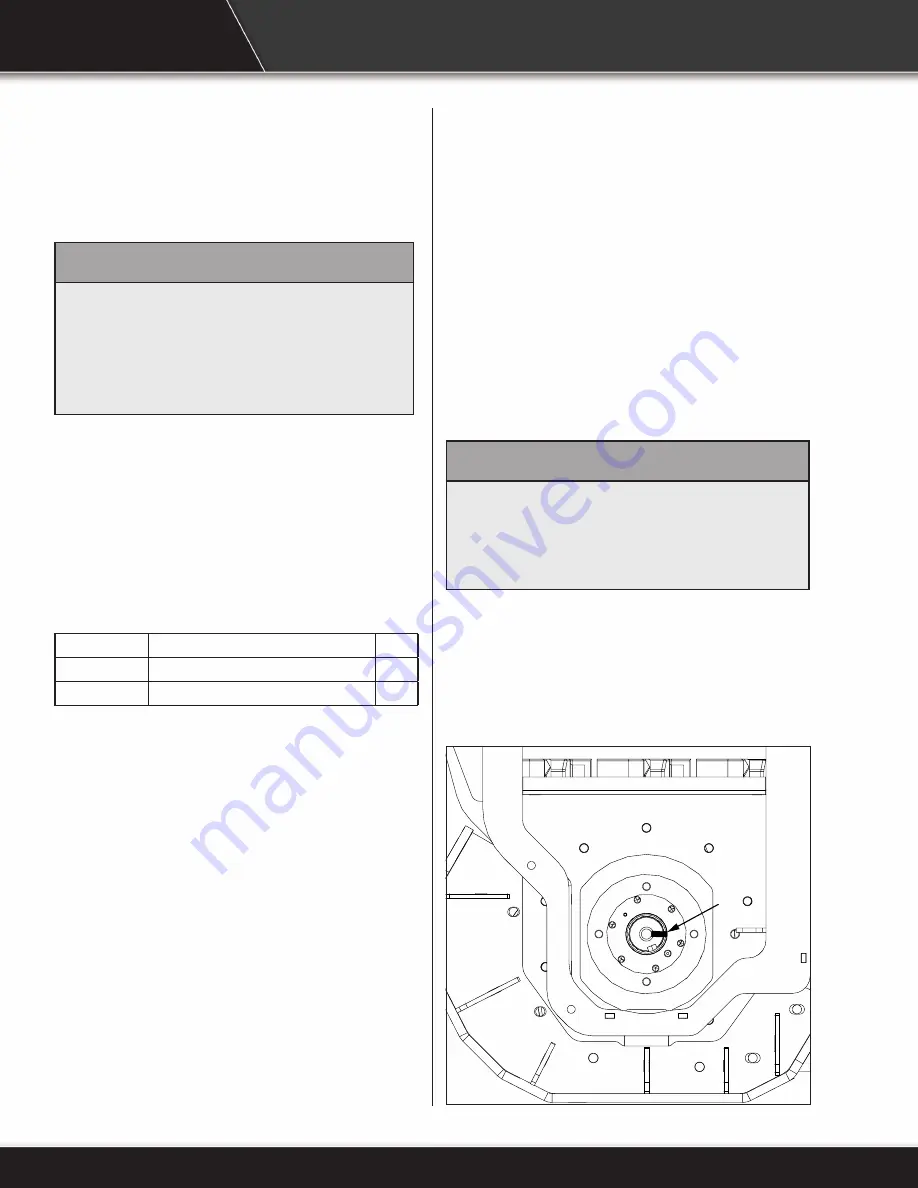
1. 

An RPM meter is required. Open cover and 

place  reflective  tape  (A)  on  bearing  end  of 

shaft. Measuring shaft speed on the bearing 

end will provide the most accurate results. 

RPM setting from factory is 1525 RPM with 36 

GPM.

A

10

Summary of Contents for iMS760

Page 1: ...iMS760 MS960 MS972 And MS1160 Brush Mulcher OPERATOR S MANUAL Issue Date October 2022...

Page 2: ...3 Maximum Allowable Case Pressure 10 4 4 Optional Two Speed Motor Setup 10 5 OPERATION 12 5 1 Preparation For Use 12 5 2 Pre Operation Check List 13 5 3 Machine Components 14 5 4 Attach To Skidsteer 1...

Page 3: ...en this machine is worn out and no longer in use it should be returned to the retailer or other party for recycling OPERATOR ORIENTATION The directions left right front and rear as mentioned throughou...

Page 4: ...voided could result in minor or moderate injury NOTICE NOTICE Indicates a situation that could result in damage to the equipment or other property 2 1 Safety Alert Symbol And Safety Words 2 2 Operatio...

Page 5: ...ly to you and your industry This manual is not to replace any regulations or laws Additional information may be found at www asae org or www osha gov If you do not understand any part of this manual c...

Page 6: ...on can occur without direct contact DO NOT leave the operator s seat if any part of the equipment contacts electric lines or cables Detach Brush Mulcher Safely Detach brush mulcher on a firm and level...

Page 7: ...roved dust mask or respirator Follow local state and federal regulations Avoid High Pressure Fluids WARNING Pressurized fluids can penetrate the skin Hydraulic hoses can fail from age damage and expos...

Page 8: ...ow lockout procedure before servicing WARNING Entanglement hazard Keep clear of moving components Wear proper protective equipment appropriate for the job WARNING Burn hazard Hot and high pressure hyd...

Page 9: ...7...

Page 10: ...h are known to the state of California to cause cancer and birth defects or other reproductive harm For more information go to www P65Warnings ca gov D005262 The two and four panel safety decals are p...

Page 11: ...ating machine D005125 D D005255 WARNING Rotating blade hazard Keep back 75 m while machine is operating Wait for blade to stop before approaching machine D005223 75 M E D005120 WARNING Rotating parts...

Page 12: ...ort on block B port on motor C950 A port on block B port on motor C970 A port on block B port on motor 4 3 Maximum Allowable Case Pressure C930 100 psi case drain required C940 100 psi case drain requ...

Page 13: ...ssary B C E F G D 6 Adjust pressure trip point setting with screw F Trip pressure is the setting where the motor switches down to the low speed high torque speed Loosen nut G and turn screw F to adjus...

Page 14: ...lts for tightness and remove all shipping tags bags skids and blocking Review and understand this manual and operating unit manual Remove any masking materials affixed during painting Inspect the mulc...

Page 15: ...aulic hoses are connected to skidsteer hydraulic couplers Each operation Check for entangled material on rotor Each operation Verify all guards doors and covers are installed and secured Each operatio...

Page 16: ...cover is removed A Spring Loaded Hose Support B Hydraulic Motor C Case Drain Burst Disk D Hydraulic And Case Drain Pressure Gauges E Quick Attach F Chain Curtain G Push Bar H Directional Felling Hook...

Page 17: ...n the correct position 4 Connect hydraulic hoses Verify hydraulic hoses are clear of pinch areas and moving parts 5 Move to a clear open area to test functions 5 5 Detach From Skidsteer WARNING Preven...

Page 18: ...w hours of use avoid hitting stones as much as possible to allow the carbide teeth A to wear slightly This can be done by keeping the cutting wheel above ground level Brand new carbide tips are razor...

Page 19: ...and a felling hook to push brush or small trees over This will allow the mulcher teeth to contact the lower portion of the brush and mulch it or cut it off The rest of the plant will be mulched as th...

Page 20: ...ark skidsteer on a level surface 2 Engage skidsteer park brake 3 Disengage hydraulic drive 4 Shut off engine and remove key WARNING Never operate brush mulcher when other people are in the vicinity Do...

Page 21: ...ing WARNING Moving parts can crush and cut Keep clear of moving components Lockout operating unit before clearing jams WARNING Never approach brush mulcher before cutting wheel has come to a complete...

Page 22: ...he flow does not power the rotor in the reverse direction it only opens the hydraulic lock on the rotor The rotor will not be powered in the reverse direction 3 Drag the rotor across sod a log or stum...

Page 23: ...gs Lubricate rotor bearings 1 pump every 250 hours of use 6 2 Inspections WARNING Prevent serious injury or death caused by unexpected movement 1 Park skidsteer on a level surface 2 Engage skidsteer p...

Page 24: ...5 To adjust belt tension loosen mounting bolts C 6 Turn bolts D to adjust belt tension 7 Belt deflection should be 0 5 in 13 mm at 3 0 lbs of force for a used belt or 4 25 lbs of force for a new belt...

Page 25: ...pulley I and belt J It may be necessary to lightly tap hub if hub stuck to shaft 9 Install belt pulley and hub onto shaft 10 Install washer E and shaft bolt D Tighten bolt 6 4 Replace Belt 11 Align pu...

Page 26: ...ct cutting teeth A for damage and wear Replace individual teeth as needed 5 Remove socket head cap screw B and tooth A Install new tooth 6 Tighten socket head cap screw B to 170 lb ft 231 Nm of torque...

Page 27: ...essurized hydraulic fluid to the atmosphere The zero leak relief valve will self reset after hydraulic pressure reduced WARNING Pressurized fluids can penetrate the skin Keep bystanders away from mach...

Page 28: ...ricating periods as dictated by experience Generally a lower quantity of grease at frequent intervals is more effective than a greater quantity at extended lubrication intervals Typical lubrication qu...

Page 29: ...in skidsteer Add if necessary Oil filter plugged Replace skidsteer oil filter Relief valve not set properly Set relief pressure to motor specification Low oil flow Check flow control on skidsteer See...

Page 30: ...t 3 Check condition of cutting teeth Replace as necessary See Service and Maintenance section 4 Check for loose or missing hardware 5 Paint parts as necessary 8 1 Storing Mulcher 1 Review Operator s m...

Page 31: ...nd including loss of profits The manufacturer is under no circumstances liable for carrier unit damage of any kind The manufacturer is not liable for the maintenance of the product This warranty is ex...

Page 32: ...4575 Powell Rd Wallenstein Ontario Canada N0B 2S0 Phone 519 698 9864 Toll Free 866 820 5603 Fax 519 698 1087 www baumalight com For parts specifications and the latest machine information please visit...

Reviews: