


Pixel Data Formats
76
Basler scout light
7.2
Pixel Data Formats
7.2.1
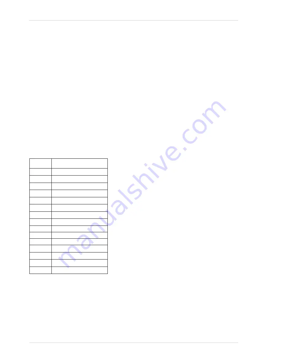
Mono 8 Format
(Equivalent to DCAM Mono 8)
When a monochrome camera is set for the Mono 8 pixel data format, it outputs 8 bits of brightness
data per pixel.
The table below describes how the pixel data for a received frame will be ordered in the image buffer
in your PC when the camera is set for Mono8 output.
The following standards are used in the table:
P
0
= the first pixel transmitted by the camera
P
n
= the last pixel transmitted by the camera
B
0
= the first byte in the buffer
B
m
= the last byte in the buffer
Byte
Data
B
0
Brightness value for P
0
B
1
Brightness value for P
1
B
2
Brightness value for P
2
B
3
Brightness value for P
3
B
4
Brightness value for P
4
B
5
Brightness value for P
5
B
6
Brightness value for P
6
B
7
Brightness value for P
7
•
•
•
•
•
•
B
m-3
Brightness value for P
n-3
B
m-2
Brightness value for P
n-2
B
m-1
Brightness value for P
n-1
B
m
Brightness value for P
n
Summary of Contents for slA1000-30fm
Page 4: ......
Page 24: ...Software and Hardware Installation 16 Basler scout light...
Page 26: ...Tools for Changing Camera Parameters 18 Basler scout light...
Page 82: ...Image Acquisition Control 74 Basler scout light...
Page 106: ...I O Control 98 Basler scout light...
Page 140: ...Standard Features 132 Basler scout light...
Page 158: ...Troubleshooting and Support 150 Basler scout light...
Page 160: ...Revision History 152 Basler scout light...
Page 162: ...Feedback 154 Basler scout light...
Page 166: ...Index 158 Basler scout light...