1-8
BE1-51/27R - General Information
I
(50
X tap value or 500 A, whichever is less)
T
MODEL AND STYLE NUMBER DESCRIPTION
BE1-51/27R Time Overcurrent Relays electrical characteristics and operational features are defined by a
combination of letters and numbers that make up its style number. The model number, together with the
style number, describe the options included in a specific device, and appear on the front panel, drawout
cradle, and inside the case assembly. Upon receipt of a relay, be sure to check the style number against
the requisition and the packing list to ensure that they agree.
Style number identification chart (Figure 1-1) defines the electrical characteristics and operational features
included in BE1-51/27R relays. For example, if the style number were U3E Z1P B1C1F, the device would
have the following:
(U)
-
3-phase-and-neutral current; 3-phase, 4-wire voltage restraint
(3)
-
Sensing input range of 1.5 to 12.0 A for phase, 0.5 to 4.0 A for neutral.
(E)
-
N.O. outputs.
(Z1) -
Sixteen position switch selects B and C (curves B1 - B8 and C1 - C8) time overcurrent
characteristic curves.
(P)
-
Operating power derived from 125 Vdc or 100/120 Vac.
(B)
-
Current operated targets.
(1)
-
One instantaneous element.
(C)
-
Push-to-energize outputs.
(1)
-
N.O. auxiliary timed output relay.
(F)
-
Semi-flush mounting.
SPECIFICATIONS
BE1-51/27R Time Overcurrent Relays electrical and physical specifications are as follows:
Repeatability
All functions, ±2%.
Voltage Sensing Inputs
Rated for 160 Vac continuous at 40 to 70 Hz (nominal frequency 50 or 60
Hz), with a maximum burden of 1 VA.
Sensing Input Burden
Less than 0.1 ohms per phase or neutral.
Sensing Input Rating
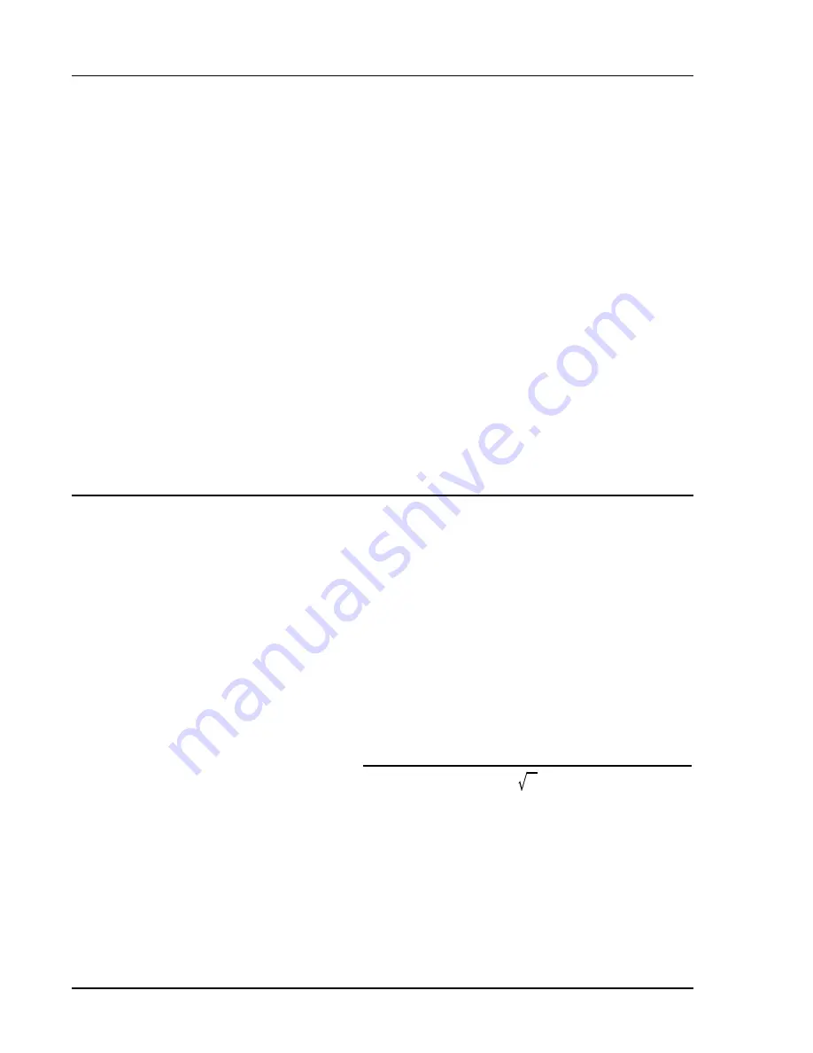
Maximum 1 second current rating is 50 X (times) maximum tap current se-
lected, or 500 A, whichever is less. Maximum continuous current is 20 A.
For ratings other than those specified by the time curves, rating is a calcu-
lated as follows:
Where: I = Maximum Current, and T = Current Flow in Seconds
Time Overcurrent Pickup
Continuously adjustable over the current sensing input ranges specified
Selection Range
in the Style Chart (Figure 1-1).


