5-2
BE1-50 Testing
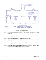
Figure 5-1. Test Circuit Connection
Step 3.
Apply sensing current (near zero) and slowly increase the sensed current until the test indicator
changes state.
Result: Current indicated by the ammeter is within two percent of the low end of the sensing
range. If present, the target indicator for the tested phase (or neutral) should be
actuated.
Step 4.
Turn the pickup adjustment fully CW. Reset target indicators if present.
Step 5.
Apply sensing current (near zero) and slowly increase the sensed current until the test indicator
changes state.
Result: Current indicated by the ammeter is within two percent of the high end of the sensing
range. If present, the target indicator for the tested phase (or neutral) should be
actuated.
Step 6.
Repeat Steps 2 through 5 for each phase and neutral as necessary for your style relay. (Neutral
sensing ranges may be different than the phase sensing range.)
Summary of Contents for BE1-50
Page 1: ... 05647 6 10 07 14 056 06 0 175 18 4 744 06 4 Publication 9 1710 00 990 Revision C 11 98 ...
Page 5: ...iv BE1 50 Introduction CONTENTS Continued SECTION 7 MANUAL CHANGE INFORMATION 7 1 Changes 7 1 ...
Page 12: ...2 2 BE1 50 Human Machine Interface Figure 2 1 Location of Controls and Indicators ...
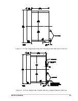
Page 20: ...BE1 50 Installation 4 5 Figure 4 7 S1 Case Single Ended Panel Drilling Diagram Rear View ...
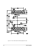
Page 21: ...4 6 BE1 50 Installation Figure 4 8 S1 Case Double Ended Panel Drilling Diagram Rear View ...
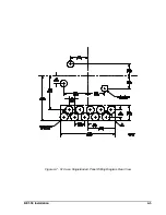
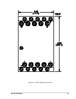
Page 22: ...BE1 50 Installation 4 7 Figure 4 9 Outline Dimensions Rear View ...

