BE1-50 Manual Change Information
7-1
SECTION 7 • MANUAL CHANGE INFORMATION
CHANGES
Substantive changes in this manual to date are summarized in the following table.
Table 7-1. Summary of Changes
Revision
Summary of Changes
ECA (ECO)/Date
B
Added UL Recognition statement, page 1-5 and added new
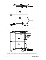
Figures 4-6 through 4-9.
13261/06-93
C
Deleted all references to Service Manual. Updated Style Chart by
adding Option 3-6 Power Supply Status Output, changing Power
Supply Type T from “230 Vac” to “240 Vac,” deleted “Selectable”
from Type S, and added Note 6. Deleted 500 Vdc from Output
Circuits in
Specifications. Added Note* to Table 1-1. Added new
power supply information and Fast Transient to
Specifications.
Corrected Figure 2-1 from “Instantaneous Undercurrent Relay” to
“Instantaneous Overcurrent Relay.” Added new power supply
information to Section 3 starting with “Basler Electric enhanced the
power supply design...” Divided
Section 4, Installation into two
sections
Section 4, Installation and Section 5, Testing. Added new
dimension figures to include all options available (S1 Single-Ended
and Double-Ended, and both mounting positions) to Section 4.
Changed Output Connection diagrams to include Sensing Type E
or G and Output F or H, Sensing Type J and Output J or K, and
Sensing Type F and output E or G. Corrected minor errors and
changed the format of the manual.
1639/11-98
Summary of Contents for BE1-50
Page 1: ... 05647 6 10 07 14 056 06 0 175 18 4 744 06 4 Publication 9 1710 00 990 Revision C 11 98 ...
Page 5: ...iv BE1 50 Introduction CONTENTS Continued SECTION 7 MANUAL CHANGE INFORMATION 7 1 Changes 7 1 ...
Page 12: ...2 2 BE1 50 Human Machine Interface Figure 2 1 Location of Controls and Indicators ...
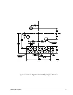
Page 20: ...BE1 50 Installation 4 5 Figure 4 7 S1 Case Single Ended Panel Drilling Diagram Rear View ...
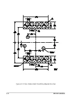
Page 21: ...4 6 BE1 50 Installation Figure 4 8 S1 Case Double Ended Panel Drilling Diagram Rear View ...
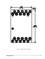
Page 22: ...BE1 50 Installation 4 7 Figure 4 9 Outline Dimensions Rear View ...

