background image


Cleaning and Maintenance 

84 / 86 

117900 

EN 


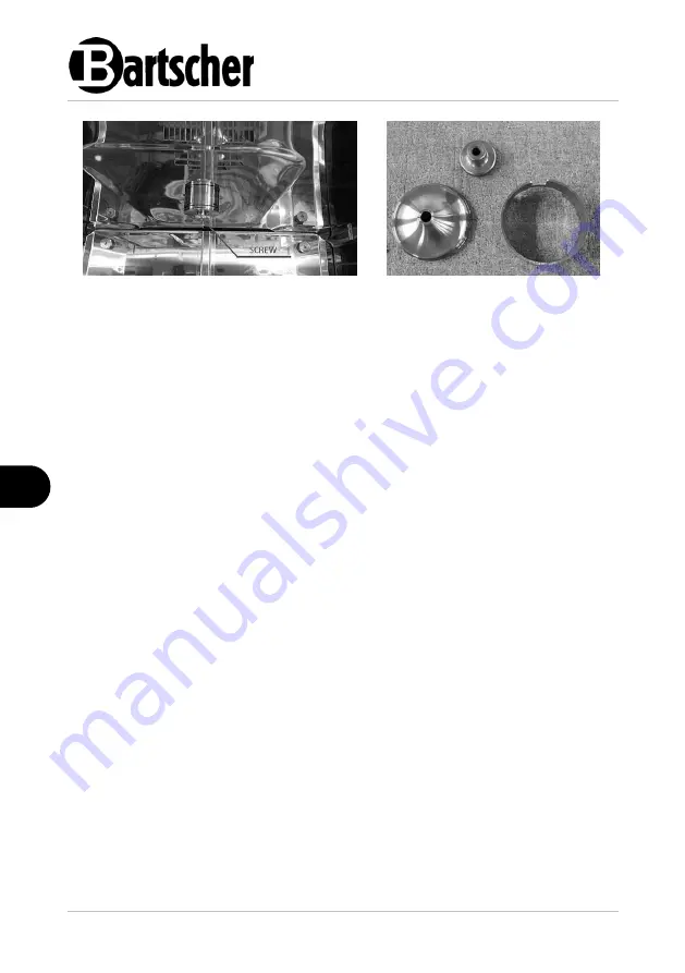
Fig. 50 

Fig. 51 


7.3


Maintenance 


ATTENTION! 

The following maintenance and cleaning work must only be carried out by 
qualified and specialised personnel and never by the user of the 
appliance! 


Cleaning the Condensate Collecting Tank with Trap at the Oven Rear Wall 
 

Every 3

–6 months, a preventive service inspection and cleaning of the outlet 

channel and the condensate collecting tank with trap, located at the rear of the 
oven, should be carried out. 

The service technician should carry out the following steps: 

–  cool the oven down to room temperature before maintenance work; 
–  disconnect the oven from the main electricity supply; 
–  find the condensate collecting tank with the trap at the rear wall of the 

oven for cleaning; 


–  unscrew the trap lid; 
–  clean the condensate collecting tank; 
–  clean the ends of all the supply lines to the trap lid; 
–  screw the cover back on; 
–  finally, check that all wires have been returned to their original positions 

and that all connections have been tightened securely.  


Summary of Contents for MC6040-5

Page 1: ...MC6040 5 MC6040 8 MC6040 10 HC6040 5 HC6040 8 HC6040 10 117900 117901 117902 117905 117906 117907...

Page 2: ...cher GmbH Franz Kleine Str 28 D 33154 Salzkotten Germany Phone 49 5258 971 0 Fax 49 5258 971 120 Technical Support Hotline 49 5258 971 197 www bartscher com Version 1 0 Date of preparation 2022 09 05...

Page 3: ...very Check 9 3 2 Packaging 9 3 3 Storage 9 4 Technical Data 10 4 1 Technical Specifications 10 4 2 List of Components of the Appliance 20 4 3 Functions of the Appliance 23 5 Installation Instructions...

Page 4: ...included in this manual is a prerequisite for safe and proper handling of the appliance Additionally accident prevention occupational health and safety and legal regulations in force in the area the...

Page 5: ...DANGEROUS VOLTAGE Dangerous voltage inside Contact leads to electric shock or burns Before performing maintenance and cleaning works the system must be switched off and locked Failure to observe thes...

Page 6: ...he rating plate correspond with the mains voltage To avoid short circuit the appliance should be kept dry If there are malfunctions during operation disconnect the appliance from the power supply Do n...

Page 7: ...ith water if the appliance is connected to the power supply Following extinction of fire ensure sufficient fresh air inflow Hot Surfaces Surfaces of the appliance become hot during operation Burning h...

Page 8: ...cal condition is flawless and allows for safe operation The appliance may only be used when all connections are executed according to rules of law in force The appliance may only be used when it is cl...

Page 9: ...uitable food products 1 4 Unintended Use An unintended use may lead to personal injuries or property damages caused by hazardous voltage fire or high temperature The appliance may only be used to perf...

Page 10: ...troduced by the user usage of unapproved spare parts We reserve the right to introduce technical modifications to the product intended for improvement of the appliance and its performance 2 2 Copyrigh...

Page 11: ...used to store the appliance when relocating or when shipping the appliance to our service point in the case of any damages The packaging and its elements are made of recyclable materials Particularly...

Page 12: ...ke instantaneous switching the fan off within 1 second prevents loss of heat energy in the event of a sudden opening of the appliance door and thus a drop in temperature in the baking chamber The poss...

Page 13: ...the steam remains in the baking chamber for as long as needed to evenly moisten each individual bakery product The efficiency of the steam from the baking chamber generated in the steam generator Stea...

Page 14: ...ur extraction position Steaming set in a program manual manual selection of steaming system only in 117905 117906 117907 appliances Steam generators direct injection Steam Box only in 117905 117906 11...

Page 15: ...ported back wall guide rails may be removed double door glazing consistent results when the baking chamber is full Important indications installation kit LBO010 or LBO020 is required for the operation...

Page 16: ...between guide rail pairs in mm 90 Temperature range max in C 250 Temperature control in C increments 1 Power output in kW 11 Number of programs pre installed for programming manually set 15 84 1 Numb...

Page 17: ...between guide rail pairs in mm 90 Temperature range max in C 250 Temperature control in C increments 1 Power output in kW 15 Number of programs pre installed for programming manually set 15 84 1 Numb...

Page 18: ...etween guide rail pairs in mm 85 Temperature range max in C 250 Temperature control in C increments 1 Power output in kW 2 x 9 55 Number of programs pre installed for programming manually set 15 84 1...

Page 19: ...between guide rail pairs in mm 90 Temperature range max in C 250 Temperature control in C increments 1 Power output in kW 11 Number of programs pre installed for programming manually set 15 84 1 Numb...

Page 20: ...between guide rail pairs in mm 90 Temperature range max in C 250 Temperature control in C increments 1 Power output in kW 15 Number of programs pre installed for programming manually set 15 84 1 Numb...

Page 21: ...etween guide rail pairs in mm 85 Temperature range max in C 250 Temperature control in C increments 1 Power output in kW 2 x 9 55 Number of programs pre installed for programming manually set 15 84 1...

Page 22: ...2 Fan 3 Water spray nozzle 4 LED lighting 5 Appliance door lock 6 Door handle 7 Appliance door 8 Height adjustable feet 4 pcs 9 Guide rails 10 Thermal processing chamber bottom 11 Thermal processing c...

Page 23: ...4 LED lighting 5 Appliance door lock 6 Door handle 7 Appliance door 8 Height adjustable feet 4 pcs 9 Guide rails 10 Thermal processing chamber bottom 11 Thermal processing chamber water drain 12 Drai...

Page 24: ...on the appliance with important information about the oven and hazardous areas as shown in the following figure Fig 1 A Baking chamber protection B Generator protection C Hood connection D Internet c...

Page 25: ...hamber the possibility to choose between different fan speeds creates optimal conditions for the most delicate and demanding baked goods 99 programs 6 baking phases and 6 parameters ensure that work p...

Page 26: ...ous to allow easy operation of the appliance The room in which the appliance will be installed must be prepared in accordance with the manufacturer s instructions The end customer must provide a locat...

Page 27: ...ns easily accessible so that they may be quickly disconnected if such a need arises Never place the appliance directly next to walls low walls division walls kitchen furniture or other surfaces made o...

Page 28: ...Installation Instructions 26 86 117900 EN Fig 2...

Page 29: ...iance may only be made by authorised personnel Safety regulations for the operation of such appliances and national regulations must be observed during installation work NOTE Please refer to the enclo...

Page 30: ...water connection is located close to the appliance 2 Prior to establishing the water connection flush the tube with enough water to remove all residues of substances that might be present in the tube...

Page 31: ...ION The appliance must be supplied with potable water to ensure correct operation in order to avoid limescale build up in the injection lines baking chamber and steam generator A connection of a softe...

Page 32: ...e condensation hood is connected by connecting the hood connection cable 4 x 0 75 mm2 to the cable gland at the back of the appliance The connection cable is connected to the marked terminals in the e...

Page 33: ...Installation Instructions 117900 31 86 EN Connection of the condensation hood power supply Fig 5 Water connection when installing the condensation hood Fig 6...

Page 34: ...ing products in the oven and when removing them from the oven Before operating and switching the oven on make sure that all safety devices are in place no part of the oven is damaged all objects which...

Page 35: ...a a si woda N ast pnie dok adnie osuszy urz dzeni e i elementy wyposa enia Setzen Sie di e Boden Abdeckung in das Becken ei n Os ona pe ni funkcj rozp r ki pomi dzy el ementem grzewczym a tack na resz...

Page 36: ...Operating Instruction 34 86 117900 EN 6 1 Operation Control Panels Fig 7 Control panel of the convection oven HC6040 Fig 8 Control panel of the convection oven MC6040...

Page 37: ...rsichtig auf den hi nteren R and des Ger tes Sworze w dolnej cz ci i n the conn ecti on box must enter the hol e i n the mai n appliance This way the connection boxis properly mounted Preparation of t...

Page 38: ...er a hol e in the mai n appliance This way the connection box is properly mounted Main Menu Screen Function Keys and Indicators Fig 11 1 NAME OF CURRENT SCREEN 2 INFORMATION BAR The name of the curren...

Page 39: ...e connection box with the heati ng element at the back edge of the appliance A pin in bottom par t of the connecti on box must enter a hol e i n the mai n appliance This way the connection box is prop...

Page 40: ...nt time 6 Current date USB Status Indicators Information about the colour USB indicator icons Black USB indicator Black colour of the icon indicates no USB communication Green USB indicator Green colo...

Page 41: ...but due to an error is not working Water Filter Status Indicator Information about the colour water filter indicator icons Green water filter indicator Green colour indicates that the water filter doe...

Page 42: ...atus of the water filter Fig 14 Water filter replacement required Status Indicators for Periodical Service Inspection Maintenance Information about the colour service indicators Green service indicato...

Page 43: ...g the acknowledge key The oven can then be used In some cases for safety reasons the warning remains permanently active until the inspection is completed In the meantime the oven cannot be used Fig 15...

Page 44: ...haltkasten mit H eizelement vorsichtig auf den hi nteren R and des Ger tes Sworze w dolnej cz ci skrzynki rozdzi elczej musi wchodzi w otw r w urz dzeniu g wnym W taki spos b skrzynka rozdzi elcza jes...

Page 45: ...perature indicator 5 Baking chamber temperature Indicator of the current baking chamber temperature 6 Baking time Indicator of the set baking time before activation of the manual baking process 7 Rema...

Page 46: ...steaming system that is not selected is blocked and dark grey 11 Vapour extraction key May be used to open or close the fume flap 12 Key for extending the baking time The baking time can be added betw...

Page 47: ...n the display The highest temperature can be set up to 250 C 3 Press the confirmation icon in the display to confirm the selected temperature The set temperature is displayed on the right side of the...

Page 48: ...d by an acoustic signal and the Baking Finished message is displayed in the information bar Fig 18 Fan Speed 1 Press the fan speed icon It changes colour to orange and the keypad is displayed 2 Use th...

Page 49: ...he display 1 To confirm the number of intervals press the multi function key or press the confirmation icon in the display 2 To add further steaming intervals during the baking process activate the Ad...

Page 50: ...colour of the icon with a white steam cloud indicates that the steam generator is ready for operation Adding Extra Steam During Baking Process If an additional steaming interval is needed after the ba...

Page 51: ...in order to evacuate excess steam from the baking chamber if necessary 1 Press the icon to open the flap The colour of the icon shows whether the vapour extractor flap is open or not The grey colour...

Page 52: ...s If the Extend Baking Time icon is pressed without setting one of the baking parameters the baking process will start for 30 seconds with the default parameters In this case the time can be extended...

Page 53: ...baking surface and slide the sheets backwards into the baking chamber This is important so that the inner glass pane is not damaged Each product on a baking sheet must have sufficient space so that th...

Page 54: ...t cool down too much before the next baking process To exit the manual baking process press the icon and the main menu screen will appear on the control panel The icon is locked during the baking proc...

Page 55: ...Setzen Sie den Schaltkasten mit H eizelement vorsichtig auf den hi nteren edg e of the appliance The pin i n the connecti on box lower part must enter the hol e i n the mai n appliance This way the co...

Page 56: ...Instruction 54 86 117900 EN Fig 22 Baking program 1 Program number 2 Program name 3 Information bar 4 Program time 5 Add steam 6 Percentage of oven load 7 Add baking time 8 Switching on 9 Stop key 10...

Page 57: ...9 baking programs Each program may consist of 6 phases of the baking process Each program has a number a name a pictogram and an activation field Fig 23 1 Image 2 Selected program 3 Program number 4 P...

Page 58: ...displayed 3 Program phases Each program may have up to 6 phases The icons are numbered from 1 to 6 and show the number of available phases White colour indicates an active phase dim colour indicates t...

Page 59: ...fan speed is displayed Press this parameter to change it The keypad will appear Use the keypad to enter the desired value and confirm by pressing the confirmation icon The fan speed can be set in the...

Page 60: ...d value Confirm by pressing the confirmation icon 12 Setting the vapour extraction flap Only one of the two different flap positions may be programmed ON OPEN or OFF CLOSE 13 AirFresh function icon Ai...

Page 61: ...baking process Select any phase icon except the first phase icon as the first phase always shows the pre heating temperature and not the total time When the phase icon is selected the screen with the...

Page 62: ...timer alarms Delete the last alarm that was added to the program by pressing the Delete Last Timer Alarm icon Confirm the action by pressing the confirmation icon in the pop up menu that appears in t...

Page 63: ...the screen or by rotating and pressing the multi function key in the cleaning menu Fig 29 1 Cleaning I This is designed for daily cleaning It lasts for approx 1 hour and 20 minutes 2 Cleaning II For i...

Page 64: ...ress Start The Start icon is displayed in green Fig 30 Fig 31 Pressing the Start icon starts the pre cleaning phase In the information bar the status changes to Preparation and the time bar shows the...

Page 65: ...tus displayed in the information bar Fig 32 Fig 33 Fig 34 WARNING Always use protective gloves when using cleaning agents Carefully read the instructions on the cleaning agent packaging Store the clea...

Page 66: ...process in progress and the remaining cleaning time Fig 32 Once the cleaning agent has been poured in it is no longer possible to stop the cleaning process so the Stop and Undo icons are locked The d...

Page 67: ...tomatically 10 seconds after the acoustic signal is generated Manual Cleaning The manual cleaning program is designed for semi automatic cleaning of soiling in the oven that cannot be removed by the a...

Page 68: ...also communicated by an acoustic signal 7 Again open the appliance door slowly and carefully 8 Spray the cleaning agent read the cleaning agent instructions carefully on the inner surfaces of the bak...

Page 69: ...options Fig 36 Fig 35 Fig 36 1 LOG IN OUT This option is intended for specialised personnel who have access rights to locked options 2 SCREEN BRIGHTNESS Press the screen brightness icon to set the scr...

Page 70: ...anguage 7 AUTO PREHEATING This option allows you to set an automatic preparation process at a specific time e g in the morning before the start of the working day Please read the following section onl...

Page 71: ...s etc 2 PASSWORD Passwords for service use 3 SOUND Buzzer settings on off 4 GENERAL SETTINGS Condensation hood settings door lock vapour hood flap steam settings 5 TEMPERATURE Setting of maximum and m...

Page 72: ...communication etc 13 STATISTICS All data for man hours days to service 14 CONTROL SETUP Contains the I O menu for service Activating Timer for Automatic Pre Heating Pre heating the oven is a function...

Page 73: ...d the parameter automatically switches to OFF 2 START TIME Parameter 16 08 can be used to set the time by which the appliance should be ready for operation 3 START DAY Parameter 16 09 shows the day on...

Page 74: ...LECTION Indicator of the day for which automatic pre heating is activated 2 TIME Shows the time for which the appliance is ready for operation 3 PROGRAM NUMBER Shows the number of the selected program...

Page 75: ...btain the password USB Transfer 1 To transfer a program go to the main menu 2 Insert the USB drive into the USB port on the left side of the appliance In the main menu the USB icon in the status bar m...

Page 76: ...drive 6 If pictograms and sounds are also to be transferred to another oven SOUND and IMAGES must be selected before transferring The options LOGS or PARAMETERS cannot be selected with the admin passw...

Page 77: ...information bar The information bar shows the name and number of the error that occurred Fig 43 The first phase should be to reset the program 1 Press the Stop icon to end the baking program 2 Return...

Page 78: ...emperature too high AN ERR12 TP3 UNDR Sensor temperature too low AN ERR27 PHLOSS L1 L1 voltage too low AN ERR28 PHLOSS L2 L2 voltage too low AN ERR29 PHLOSS L2 L3 voltage too low AN ERR30 Water level...

Page 79: ...9 TP4 OVRH AN ERR50 TP5 OVRH AN ERR51 TP6 OVRH AN ERR52 TP7 OVRH AN ERR53 TP8 OVRH AN ERR54 TP9 OVRH AN ERR55 TP10 OVRH AN ERR56 TRIAC1 28 AN ERR57 TRIAC1 35 AN ERR58 TRIAC1 36 AN ERR59 TRIAC1 37 AN E...

Page 80: ...knife fork etc Sharp or pointed implements may damage the appliance and when in contact with live parts they may cause electric shock For cleaning do not use any scouring agents that contain solvents...

Page 81: ...fore cleaning The following appliance components must be cleaned daily door seals inner glass pane of the appliance door inner side of the appliance door baking chamber control panel LED interior ligh...

Page 82: ...loth Use a mild cleaning agent when required Wipe with a clean cloth and dry the cleaned surfaces 5 After cleaning close the inner glass pane and fasten both locking latches 6 Check again that the inn...

Page 83: ...cleaned daily after the cleaning process or before the start of the working day Use a damp cloth to clean the condensate collecting tank to remove soiling dust and accumulated water Ensure that the wa...

Page 84: ...of the oven with a damp soft cloth or with a mild cleaning agent for degreasing metal surfaces 2 Clean the outside of the door glass with a damp soft cloth or with a mild glass cleaning agent Baking C...

Page 85: ...Heating elements and temperature sensors must not be cleaned Fig 49 6 After cleaning re install the rear wall fan cover back in place and fix it four fixing screws manually without using tools 7 Final...

Page 86: ...ting tank with trap located at the rear of the oven should be carried out The service technician should carry out the following steps cool the oven down to room temperature before maintenance work dis...

Page 87: ...cleaning of the electrical part of the oven must only be carried out by a qualified electrician taking into account the following phases cool the oven down to room temperature disconnect the oven from...

Page 88: ...ppliances must be disposed of and recycled in a correct and environmentally friendly manner You must not dispose of electric appliances with household waste Disconnect the appliance from the power sup...

Reviews: