background image


DEUTSCH 

DE 


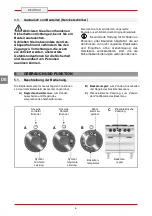
5.2. 

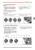
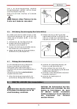
Zündung der Gasherdbrenner 

ZÜNDUNG 


A) 

Den Drehregler des gewünschten Gasherd-
brenners drücken und nach links drehen, um 
die Zündflamme zu zünden (

Position 1

). Die 

Zündflamme mit Hilfe eines Streichholzes 
entzünden. 

B) 

Drehregler etwa 10 Sekunden lang gedrückt 
halten, um das Thermoelement aufzuheizen; 
dann den Drehregler loslassen. 
 

C) 

Drehregler zum Zünden des Gasherdbrenners 
nach links drehen (

Position 2

). 

D) 

Leistung des Gasherdbrenners einstellen 
(

Position 3

). 


AUSSCHALTEN 


A) 

Drehregler  zum  Ausschalten  des  Gasherd- 
brenners nach rechts drehen (Position 1). 

B) 

Drehregler  zum  Ausschalten  der  Zündflamme 
nach rechts drehen (Position 0). 


5.3. 

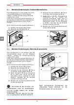
Anzünden der Backofen-Gasbrenner 


A) 

Drehregler drücken und nach links drehen und 
gleichzeitig  mehrmals  die  piezoelektrische 
Zündung  (

C

)  betätigen,  um  die  Zündflamme 

anzuzünden  (Position 

1

).  Drehregler  ca.  10 

Sekunden  gedrückt  halten,  damit  sich  das 
Thermoelement aufheizen kann. 


Hinweis:  Das  Anzünden  der  Zündflamme 
kann  auch  manuell  mit  Hilfe  eines 
Streichholzes  durch  den  Deckel  auf  dem 
Backofenboden erfolgen

B) 

Drehregler  nach  links  drehen,  zwischen 
60  °C  und  280  °C  einstellen  und  vor 
Verwendung  des  Backofens  Vorheizzeit 
abwarten (Position 2). 


Temperatur °C 

60 

90 

120 

160 

200 

240 

280 

300 

Zeit in Minuten 

12 

15 

18 

22 

26 


Pos 0 

Pos 1 

Pos 2 

ID 05 

Pos 1 

Pos 2 

Pos 3 

Pos 0 

ID 04 

Summary of Contents for 2951121

Page 1: ...GS UND W ARTUNGSANW EISUNGEN INSTALLATION OPERATING AND MAINTENANCE NSTRUCTIONS MANUEL D INSTALLATION D UTILISATION ET D ENTRETIEN MANUALE DI INSTALLAZIONE USO E MANUTENZIONE MANUAL DE INSTALACI N USO...

Page 2: ...ODIFICATIONS TECHNIQUES CI RISERVIAMO LA POSSIBILIT DI INTRODURRE MODIFICHE TECNICHE SE RESERVA EL DERECHO A INTRODUCIR MODIFICACIONES T CNICAS SUJEITO A ALTERA ES T CNICAS TECHNISCHE WIJZIGINGEN VOOR...

Page 3: ...ackung und Auspacken 11 8 2 Installation Servicetechniker 11 8 3 Ableitung der Verbrennungsprodukte 12 8 4 Montage des Ger ts in Reihe 12 8 5 Gasanschluss Servicetechniker 12 8 6 Umr stung Gasversorgu...

Page 4: ...NG DES GER TS 17 F FUNKTIONSST RUNGEN 10 G Gasanschluss 12 Ger tebeschreibung 4 I Installation 11 M Minimum Einstellung des Backofen Brennerhahns 14 Minimum Einstellung des Kochfeld Brennerhahns 14 Mo...

Page 5: ...den Gebrauch bestimmt f r den es entworfen wurde jeder andere Gebrauch ist als unsachgem anzusehen Der Hersteller lehnt jede Haftung f r Sch den an Sachen oder Personen ab die durch unsachgem en oder...

Page 6: ...en Symbole benutzt deren Bedeutung im Folgenden beschrieben wird Warnung Weist auf wichtige Sicherheits hinweise hin Um die Gesundheit und Sicherheit der Personen nicht zu gef hrden und keine Sch den...

Page 7: ...Sicher heitsvorrichtungen ordnungsgem eingesetzt und funktionst chtig sind 4 4 Typenschild Das abgebildete Typenschild ist direkt am Ger t angebracht Darauf sind alle f r die Betriebssicherheit erfor...

Page 8: ...f den Einsatz von nicht originalen Ersatzteilen und Eingriffen ohne Genehmigung des Herstellers zur ckzuf hren sind die die Sicherheitsanforderungen ver ndern k nnen 5 GEBRAUCH UND FUNKTION 5 1 Beschr...

Page 9: ...tion 1 B Drehregler zum Ausschalten der Z ndflamme nach rechts drehen Position 0 5 3 Anz nden der Backofen Gasbrenner A Drehregler dr cken und nach links drehen und gleichzeitig mehrmals die piezoelek...

Page 10: ...richtungen die wenn sie aktiviert werden unerwartete Gefahrensituationen f r die Sicherheit und Gesundheit von Personen ausl sen k nnen 6 2 Ordentliche Wartung Die ordentliche Wartung besteht in der t...

Page 11: ...nners vor Eindringen von Wasser und Schmutz um Fehl funktionen des Gasbrenners oder die Verstopfung der D se zu vermeiden 6 4 Reinigung des Backofens In kaltem Zustand k nnen der Backofenboden und die...

Page 12: ...den Rohrleitungen nach langer Nichtbenutzung Die Z ndflamme geht immer wieder aus Das Thermoelement ist nicht hei genug Den Anz ndvorgang verl ngern Die Z ndflamme z ndet aber der Brenner z ndet nicht...

Page 13: ...kzeugen ein damit Besch digungen der darunter liegenden Stahlblechpaneele vermieden werden Ziehen Sie die Kartonverpackung nach oben vom Ger t ab Pr fen Sie nach dem Auspacken ob die Ausstattung des G...

Page 14: ...ss eine Blockierung des Ansaugl fters gleichzeitig die Unterbrechung der Gaszufuhr ausl st F r die Installation von Gasherden vom Typ A ist kein Anschluss an eine Rauchabzugsanlage vorgesehen sondern...

Page 15: ...ition 4 des Typenschildes 8 7 Pr fung Servicetechniker Vor der Inbetriebnahme ist eine Pr fung der Anlage vorzunehmen um die Betriebs bedingungen jedes einzelnen Bauteils zu beurteilen und eventuelle...

Page 16: ...fen Brennerhahns Diese Einstellung ist nur vorzunehmen wenn die anzuschlie ende Gasart von der Pr fgasart abweicht nachdem die Versorgungsumr stung vorgenommen wurde Pr fen Sie vor Ausf hrung dieser E...

Page 17: ...Sie bei Bedarf die D se G durch eine die f r die Art des verwendeten Gases geeignet ist siehe Anlagen Ziehen Sie die Schraube E fest und stellen Sie am Ende den Anfangszustand wieder her 9 4 Austausch...

Page 18: ...i Rohrs D ein Ziehen Sie Schraube C fest und stellen Sie am Ende den Anfangszustand wieder her 9 6 Austausch Z ndflammend se Backofenbrenner Gehen Sie hierzu auf die angegebene Weise vor Schlie en Sie...

Page 19: ...eses Produkt nicht wie normaler Hausm ll behandelt werden darf sondern der entsprechenden Sammelstelle zum Recycling von Elektro und Elektronik Ger ten zugef hrt werden muss Beachten Sie die rtlichen...

Page 20: ......

Page 21: ...ing and unpacking 11 8 2 Installation service technician 11 8 3 Extraction of fumes 12 8 4 Installation of the appliance in a line 12 8 5 Gas connection service technician 12 8 6 Switching into differ...

Page 22: ...nition of gas stove burners 7 Ignition of oven burners 7 Inspection 13 Installation 11 Installation of the appliance in a line 12 M Minimum setting of the hob burner valve 14 Minimum setting of the ov...

Page 23: ...any other use is considered as the use not in compliance with the intended use The manufacturer is not liable for material damage or damage to person caused by misapplication or incorrect application...

Page 24: ...mation or draw attention to essential data Caution warning Indicate important safety instructions You should acquire the proper conduct to prevent hazard against people health and safety or not to cau...

Page 25: ...day that the protection devices are mounted correctly and operational 4 4 Rating plate The rating plate shown in the drawing is fixed directly on the device It includes all guidelines and information...

Page 26: ...s than original or intervention into the appliance without the manufacturer s consent that may have altered the safety requirements 5 USE AND OPERATION 5 1 Description of the controls The elements con...

Page 27: ...stove burner off position 1 B To put out the ignition flame rotate the control knob clockwise position 0 5 3 Ignition of oven burners A Press the control knob and turn it left while simultaneously pr...

Page 28: ...e of activation may lead to unexpected situations endangering the safety and health of people 6 2 Proper maintenance Proper maintenance includes daily cleaning of all components which have contact wit...

Page 29: ...and replace all elements Protect the interior of the gas stove burner against water and dirt to avoid malfunction and clogging of nozzles 6 4 Cleaning of the oven When the oven is cold remove bottom...

Page 30: ...e pipes in connection with the long downtime The igniting flame continuously goes out The thermal element is not sufficiently hot Extend the ignition process The ignition flame burns but the igniter d...

Page 31: ...carton box It may damage the stainless steel inside the box Remove the carton packaging from bottom to top When unpacked check if the appliance is according to the order In case of any difference inf...

Page 32: ...cted in such way that lock of suction fan interrupts the gas supply Installation of stoves of type A does not envisage connection to the fume exhaust system but to the appropriate extraction hood whic...

Page 33: ...apply a new sticker which includes used gas type item 4 of the rating plate 8 7 Inspection service technician Before starting the device the installation check up should be run to evaluate the working...

Page 34: ...mum setting of the oven burner valve These settings are required only if the connected gas type differs from the factory preset and checked gas after switching to the different gas type Before perform...

Page 35: ...ipe F When required replace the nozzle G with a nozzle intended for used gas see appendices Tighten the screw E and restore the initial settings 9 4 Replacement of the ignition flame nozzles of the ga...

Page 36: ...w C and set the Venturi pipe D Tighten the screw C and restore the initial settings 9 6 Replacement of the ignition flame nozzle of the oven burners Follow the instructions below Close the gas cut off...

Page 37: ...roduct or attached manual indicates that the product cannot be considered as ordinary household waste and should be transferred to a special collection point for electrical and electronic appliances f...

Page 38: ......

Page 39: ...tallation technicien de service 11 8 3 vacuation des produits de combustion 12 8 4 Montage de l appareil en s rie 12 8 5 Raccordement du gaz technicien de service 12 8 6 R armement pour un autre type...

Page 40: ...de l appareil en s rie 12 N Nettoyage de la plaque cuisson 9 Nettoyage du four 9 P Plaque signal tique 5 R Raccordement du gaz 12 R armement pour un autre type de gaz 13 Recommandations g n rales 4 R...

Page 41: ...usage est consid r comme une utilisation non conforme Le fabricant d cline toute responsabilit pour les dommages mat riels ou aux personnes caus s par une utilisation non conforme ou incorrecte de l a...

Page 42: ...fication est pr sent e ci dessous Avertissement Indique des consignes de s curit importantes Suivre les proc dures correctes afin d viter tout risque pour la sant et la s curit des personnes ainsi que...

Page 43: ...rectement 4 4 Plaque signal tique La plaque signal tique pr sent e sur le dessin est fix e directement sur l appareil Sur la plaque signal tique sont indiqu es toutes les consignes et informations n c...

Page 44: ...r l appareil sans l autorisation du fabricant qui ont pu modifier les exigences de s curit 5 UTILISATION ET FONCTIONNEMENT 5 1 Description de la commande Les l ments de commande pour les fonctions les...

Page 45: ...teur droite position 1 B Pour teindre la flamme d allumage tourner le r gulateur du br leur droite position 0 5 3 Allumage des br leurs du four A Appuyer sur le r gulateur et le tourner gauche en m me...

Page 46: ...tions impr vues dangereuses pour la sant des personnes 6 2 Entretien correct technicien de service L entretien correct inclut le nettoyage quotidien de toutes les pi ces de l appareil qui entrent en c...

Page 47: ...nts Prot ger l int rieur du br leur gaz contre la p n tration de l eau et de la salet pour viter un fonctionnement incorrect du br leur et l obstruction des buses 6 4 Nettoyage du four Lorsque le four...

Page 48: ...ement De l air dans les conduits suite un arr t prolong La flamme d allumage s teint constamment L l ment thermique n est pas assez chaud Prolonger le temps d allumage La flamme d allumage br le mais...

Page 49: ...on l aide d un outil tranchant Cela peut endommager la t le inox se trouvant l int rieur Retirer l emballage en carton en le tirant vers le haut Une fois l appareil d semball v rifier si le contenu es...

Page 50: ...it tre raccord de fa on ce que le verrouillage du ventilateur aspirant entra ne en m me temps la coupure d arriv e de gaz Les cuisini res de type A ne n cessitent pas de raccordement l installation d...

Page 51: ...elle qui indique le gaz utilis position 4 de la plaque signal tique 8 7 Contr le technicien de service Avant de mettre en marche l appareil contr ler l installation pour valuer les conditions d exploi...

Page 52: ...gulateur A 9 2 R glage minimal de la vanne du br leur du four Ces r glages sont n cessaires seulement si le type de gaz raccord est diff rent du gaz utilis et contr l en usine apr s le raccordement d...

Page 53: ...remplacer la buse G par une buse utilis e pour le type de gaz donn voir les annexes Visser la vis E et retourner enfin aux r glages initiaux 9 4 Remplacement de la buse de la flamme d allumage des br...

Page 54: ...a vis C et placer le tube de Venturi D Visser la vis C et enfin retourner aux r glages initiaux 9 6 Remplacement de la buse de la flamme d allumage des br leurs du four Suivre la proc dure d crite ci...

Page 55: ...peut pas tre consid r comme un d chet m nager mais doit tre transmis un point de collecte d appareils lectriques et lectroniques pour qu il soit recycl Respecter les lois locales en mati re de valori...

Page 56: ......

Page 57: ...sistenza 11 8 3 Scarico dei prodotti della combustione 12 8 4 Montaggio dell apparecchiatura in serie 12 8 5 Allacciamento del gas tecnico del servizio assistenza 12 8 6 Adeguamento ad altro tipo di g...

Page 58: ...ruciatore del forno 14 Impostazione minima della valvola del fornello del piano di cottura 13 IMPOSTAZIONI 13 Indicazioni generali 4 Indicazioni relative all uso dell apparecchiatura 8 Indicazioni rel...

Page 59: ...dei danni materiali o dei danni a persone dovuti all uso non conforme o all uso erroneo dell apparecchiatura L apparecchiatura destinata unicamente all uso previsto dal fabbricante Ogni altro utilizz...

Page 60: ...ti pi significativi sono stati utilizzati simboli speciali il cui significato chiarito a seguire Avvertimento Presenta importanti indicazioni per la sicurezza Per non mettere a rischio la salute e la...

Page 61: ...ano correttamente montati e funzionanti 4 4 Targhetta nominale La targhetta nominale presentata nell immagine fissata direttamente all apparecchiatura Sulla targhetta sono riportate tutte le indicazio...

Page 62: ...nali e da ingerenze nell apparecchiatura senza il permesso del fabbricante tali da modificare i requisiti di sicurezza 5 USO E FUNZIONAMENTO 5 1 Descrizione dell uso Gli elementi di comando delle funz...

Page 63: ...pola del regolatore posizione 1 B Per spegnere la fiamma pilota ruotare verso destra la manopola del regolatore posizione 0 5 3 Accensione dei bruciatori del forno A Premere la manopola del regolatore...

Page 64: ...produrre situazioni di pericolo inaspettate tali da mettere a rischio la sicurezza e la salute umana 6 2 Corretta manutenzione La manutenzione corretta comprende la pulizia quotidiana di tutti i pezz...

Page 65: ...gere l interno del bruciatore della piastra a gas dall acqua e dallo sporco In questo modo si evitano i malfunzionamenti e il pericolo di occlusione degli ugelli 6 4 Pulizia del forno A forno freddo s...

Page 66: ...Accendere manualmente la fiamma Aria nelle condotte a causa della sosta prolungata La fiamma pilota si spegne continuamente La termocoppia non sufficientemente calda Prolungare l accensione La fiamma...

Page 67: ...a inossidabile situata all interno La confezione in cartone andr rimossa dall apparecchiatura dall alto Dopo l estrazione dall imballaggio accertarsi che l equipaggiamento dell apparecchiatura sia con...

Page 68: ...del ventilatore aspiratore fermi contemporaneamente l afflusso del gas Per l installazione delle apparecchiature di tipo A non si prevede l uso di un collegamento all impianto di aspirazione ma l uso...

Page 69: ...zzato posizione 4 della targhetta nominale 8 7 Controllo tecnico del servizio assistenza Prima di avviare l apparecchiatura effettuare un controllo dell impianto per valutare le condizioni di utilizzo...

Page 70: ...ne minima della valvola del bruciatore del forno Queste impostazioni sono richieste soltanto quando il tipo di gas collegato diverso da quello impostato verificato dopo l allacciamento dopo il passagg...

Page 71: ...un ugello adatto al tipo di gas utilizzato vedi allegati Avvitare nuovamente il bullone E e ripristinare lo stato iniziale 9 4 Sostituzione dell ugello della fiamma di accensione dei bruciatori della...

Page 72: ...e C e impostare il tubo di Venturi D Avvitare la vite C e ritornare alle impostazioni originali 9 6 Sostituzione dell ugello della fiamma di accensione dei bruciatori del forno Procedere nel modo indi...

Page 73: ...indica l impossibilit di trattare il prodotto stesso come un normale rifiuto comunale L articolo usato dovr essere trasmesso a un punto di raccolta di dispositivi elettrici ed elettronici ai fini del...

Page 74: ......

Page 75: ...t cnico de servicio 11 8 3 Evacuaci n de productos de combusti n 12 8 4 Montaje del aparato en serie 12 8 5 Conexi n de gas t cnico de servicio 12 8 6 Rearme a otro tipo de gas t cnico de servicio 13...

Page 76: ...17 Embalado 11 Encendido de los quemadores de la cocina a gas 7 Encendido de los quemadores del horno 7 Entrada de aire primario de los quemadores del horno 16 Evacuaci n de productos de combusti n 1...

Page 77: ...onsidera uso disconforme El fabricante no asume responsabilidad de da os materiales o corporales surgidos a consecuencia del uso incorrecto o err neo del aparato Cualquier trabajo relacionado con el m...

Page 78: ...ia Indica instrucciones de seguridad importantes A fin de evitar riesgos para la seguridad y salud de las personas y no causar da os adopte procedimientos adecuados Atenci n Indica la informaci n t cn...

Page 79: ...est n debidamente instalados y fiables 4 4 Placa de identificaci n La placa de identificaci n mostrada est fijada directamente en el aparato En la placa se dan todas las indicaciones e informaci n nec...

Page 80: ...parato sin autorizaci n del fabricante Tales circunstancias podr an cambiar requisitos de seguridad 5 OPERACI N Y FUNCIONAMIENTO 5 1 Descripci n de la operaci n Los elementos de control de las funcion...

Page 81: ...perilla reguladora a la derecha posici n 1 B Para apagar la llama de encendido gire la perilla reguladora a la derecha posici n 0 5 3 Encendido de los quemadores del horno A Pulse la perilla regulador...

Page 82: ...ara la salud de las personas 6 2 Mantenimiento correcto El mantenimiento adecuado incluye la limpieza diaria de todas las partes que est n en contacto con los alimentos y el mantenimiento sistem tico...

Page 83: ...uciedad el interior del quemador de la cocina a gas para evitar fallos en el funcionamiento del quemador y la obstrucci n de los inyectores 6 4 Limpieza del horno Cuando el horno est fr o se pueden re...

Page 84: ...os debido a una parada prolongada La llama de encendido se apaga continuamente El elemento t rmico no est suficientemente caliente Extender el proceso de encendido La llama se enciende pero el quemado...

Page 85: ...la chapa de acero Retire el envase de cart n hacia arriba Una vez desembalado el aparato compruebe si el equipamiento del mismo concuerda con el pedido En caso de disconformidades informe inmediatame...

Page 86: ...eber conectarse de modo que el bloqueo del ventilador cause el corte de gas al mismo tiempo A fin de instalar las cocinas de tipo A no se prev la conexi n a la instalaci n de extracci n sino un dispos...

Page 87: ...correcta de gas posici n 4 de la placa de identificaci n 8 7 Inspecci n t cnico de servicio Antes de arrancar el aparato inspeccione la instalaci n a fin de evaluar las condiciones de uso de cada uno...

Page 88: ...dora A 9 2 Ajuste m nimo de la v lvula del quemador del horno Dichos ajustes se requieren solo cuando el tipo de gas conectado es diferente del gas ajustado y comprobado en f brica una vez rearmado a...

Page 89: ...otra adecuada para gas usado ver anexos si procede Apriete el tornillo E y al final vuelva a los ajustes iniciales 9 4 Cambio del inyector de la llama de encendido de los quemadores de la cocina a gas...

Page 90: ...ubo de Venturi D Gire el tornillo C y al final vuelva a los ajustes iniciales 9 6 Cambio del inyector de la llama de encendido de los quemadores del horno Siga el procedimiento descrito a continuaci n...

Page 91: ...a documentaci n adjunta indica que el producto no podr tratarse como residuos comunales y deber entregarse a un punto de recogida autorizado de aparatos el ctrico y electr nicos para su reciclaje Resp...

Page 92: ......

Page 93: ...11 8 2 Instala o servi o t cnico 11 8 3 Condu o dos produtos da queima 12 8 4 Montagem do aparelho em s rie 12 8 5 Liga es de g s servi o t cnico 12 8 6 Convers o para outro tipo de g s servi o t cnic...

Page 94: ...D DESCARTE DO APARELHO 17 Descri o do aparelho 4 Descri o do servi o 6 Desembalar 11 Dispositivos de seguran a 5 E Embalar 11 F Forno termostato de seguran a 5 I Instala o 11 M Manuten o adequada 8 M...

Page 95: ...n o ter responsabilidade pelos danos materias ou pessoais que se derem devido utiliza o err nea ou inapropriada do aparelho Todo trabalho relacionado manuten o que demandarem uma qualifica o t cnica...

Page 96: ...u es de seguran a importantes com o fim de n o comprometer a seguran a e a sa de das pessoas e n o provocar quaisquer danos deve se seguir o procedimento adequado indicado Cuidado Indica informa es t...

Page 97: ...ncionamento 4 4 Placa de informa o Conforme apresentado na imagem a placa de informa o est fixada diretamente no aparelho Nesta placa constam todas as orienta es e informa es necess rias para o uso co...

Page 98: ...interfer ncias no produto que possa alterar seus dispositivos de seguran a sem autoriza o do fabricante 5 USO E FUNCIONAMENTO 5 1 Descri o do servi o Os elementos que controlam as principais fun es e...

Page 99: ...t o regulador para a direita posi o 1 B Para desligar a chama piloto gire o bot o regulador para a direita posi o 0 5 3 Acendimento dos queimadores do forno A Pressionar o bot o e gira lo para a esque...

Page 100: ...acesso aos aparelhos que quando ativados podem causar situa es inesperadas perigosas sa de das pessoas 6 2 Manuten o adequada Uma manuten o correta inclui a limpeza di ria de todas as pe as que t m c...

Page 101: ...nentes Proteger o interior do queimador g s da placa contra gua e sujeira para evitar o mau funcionamento do queimador ou o entupimento da boca 6 4 Limpeza do forno Quando o forno estiver frio pode se...

Page 102: ...ama manualmente Ar nos tubos causado por longos intervalos de uso Chama piloto constantemente acesa Termopar n o encontra se suficientemente quente Prolongar o processo de acendimento A chama piloto e...

Page 103: ...entas afiadas pois estas poder o causar danos lataria do aparelho A embalagem de papel o dever ser retirada por cima do aparelho Ap s desembalar verificar se o aparelho est de acordo com o que fora pe...

Page 104: ...erior que precisa ser ligado de tal forma que o bloqueio do ventilador de suc o cause de uma s vez a interrup o do fluxo de g s A fim de se instalar o dispositivo do tipo A n o se prev a utiliza o de...

Page 105: ...g s adaptado posi o 4 na tabela de identifica o 8 7 Controle servi o t cnico Antes de ligar o aparelho inspecione a instala o para avaliar as condi es operacionais de cada componente individual e ver...

Page 106: ...9 2 Configura o m nima da v lvula do queimador do forno Estas configura es s o necess rias apenas quando o tipo de g s ligado diferencia se daquele tipo de g s configurado e definido na f brica ap s a...

Page 107: ...bstitua o bocal G por um que seja adaptado para o tipo de g s utilizado ver anexo Apertar o parafuso E e no fim redefinir s configura es iniciais 9 4 Substitui o do bocal da chama piloto do queimador...

Page 108: ...r o parafuso C e instalar o tubo de Venturi D Apertar o parafuso C e no fim retornar s configura es iniciais 9 6 Substitui o do bocal de chama piloto dos queimadores do forno Proceder conforme indicad...

Page 109: ...o ou na documenta o anexa indica que o produto n o deve ser tratado como lixo dom stico comum e deve se lev lo um ponto de coleta de materiais el tricos e eletr nicos para fins de reciclagem Observe a...

Page 110: ......

Page 111: ...atie onderhoudsmonteur 11 8 3 Afvoer van de verbrandingsproducten 12 8 4 Montage van het apparaat in rij 12 8 5 Gasaansluiting onderhoudsmonteur 12 8 6 Omzetting naar een ander soort gas onderhoudsmon...

Page 112: ...in rij 12 O Omschrijving van de bediening 6 Omschrijving van het apparaat 4 Omzetting naar een ander soort gas 13 R Routine onderhoud 8 S STORINGEN 10 T Tips voor het gebruik van het toestel 8 Typepl...

Page 113: ...wd als incorrect De fabrikant aanvaardt geen enkele aansprakelijkheid voor materi le schaden of schade aan personen veroorzaakt door incorrect of onjuist gebruik van het apparaat Alle onderhoudswerkza...

Page 114: ...le symbolen gebruikt Waarschuwing Het wijst op belangrijke veilig heidsvoorschriften aan Om de gezond heid en de veiligheid van personen niet in gevaar te brengen en geen schade te veroorzaken is het...

Page 115: ...ligheidsthermostaten op juiste montage en correcte werking 4 4 Typeplaatje Het op de afbeelding weergegeven typeplaatje wordt direct op het toestel aangebracht Op het typeplaatje worden alle nodige aa...

Page 116: ...et apparaat zonder de toestemming van de fabrikant die de veiligheidsvereisten kunnen veranderen 5 GEBRUIK EN WERKING 5 1 Beschrijving van de bediening De bedieningselementen van de belangrijkste func...

Page 117: ...an de brander van de oven A Druk de draaiknop van de regulatie in en draai linksom tegelijkertijd enkele keren de pi zo elektrische ontsteking C indrukken om de ontstekingsvlam te ontsteken positie 1...

Page 118: ...rzieningen die als ze geactiveerd worden onverwachte gevaren voor de veiligheid en gezondheid van personen kunnen betekenen te verhinderen 6 2 Routine onderhoud De juiste conservatie houdt in alle ele...

Page 119: ...van de gasplaat tegen het binnendringen van water en vuil om onjuiste werking van de brander en verstoppen van de sproeier te voorkomen 6 4 Reiniging van de oven Als de oven koud is kunnen de bodem e...

Page 120: ...eidingen doordat toestel voor langere tijd niet werd gebruikt De ontstekingsvlam dooft aldoor Het thermo element is niet heet genoeg Verleng het ontstekingsproces De ontstekingsvlam brandt maar de bra...

Page 121: ...kan schade aan de roestvrij stalen platen binnen de verpakking veroorzaken Haal de kartonnen verpakking uit het apparaat van boven Controleer na het uitpakken van het apparaat of de uitrusting met de...

Page 122: ...oten dat wanneer de zuigventilator geblokkeerd is ook de gastoevoer wordt onderbroken Voor de installatie van toestellen van het type A is geen aansluiting op een rookafvoersysteem voorzien maar een g...

Page 123: ...het gebruikte gas wordt weergegeven positie 4 van het typeplaatje 8 7 Controle onderhoudsmonteur V r de ingebruikname van het apparaat controleer de installatie om elke individuele component op de goe...

Page 124: ...tiel van de brander van de oven Deze instellingen zijn alleen dan vereist als het aangesloten soort gas anders is dan het gas dat is ingesteld en gecontroleerd door de fabriek na het omzetten op een a...

Page 125: ...ikte type gas geschikt is zie bijlagen Draai schroef E aan en tot slot terugkeren naar de beginpositie 9 4 Vervanging van de sproeier van de ontstekingsvlam van de brander van de gasplaat Ga hiervoor...

Page 126: ...roef C aandraaien en tot slot terugkeren naar de oorspronkelijke staat 9 6 Vervanging van de sproeier van de ontstekingsvlam van de brander van de oven Ga hiervoor als volgt te werk Sluit het gas shut...

Page 127: ...leverde documentatie informeert dat dit product niet als huishoudelijk afval mag worden behandeld maar het moet in een bepaalde inzamelpunt voor de recycling van elektrische en elektronische apparaten...

Page 128: ......

Page 129: ...e i rozpakowanie 11 8 2 Instalacja technik serwisu 11 8 3 Odprowadzanie produkt w spalania 12 8 4 Monta urz dzenia w szeregu 12 8 5 Przy cze gazu technik serwisu 12 8 6 Przezbrojenie na inny rodzaj ga...

Page 130: ...stat bezpiecze stwa 5 Prawid owa konserwacja 8 Przezbrojenie na inny rodzaj gazu 13 Przy cze gazu 12 R Rozpakowanie 11 T Tabliczka znamionowa 5 U Urz dzenia zabezpieczaj ce 5 USTAWIENIA 13 Ustawienie...

Page 131: ...wanie jest traktowane jako niezgodne z przeznaczeniem Producent nie ponosi odpowiedzialno ci za szkody rzeczowe lub szkody na ludziach kt re powsta y na skutek nieprawid owego lub b dnego u ywania urz...

Page 132: ...pisane poni ej Ostrze enie Wskazuje na wa ne wskaz wki bezpiecze stwa Aby nie zagra a zdrowiu i bezpiecze stwu os b oraz nie spowodowa adnych szk d nale y przyswoi sobie odpowiedni spos b post powania...

Page 133: ...s prawid owo zamontowane i sprawne 4 4 Tabliczka znamionowa Przedstawiona na rysunku tabliczka znamionowa jest umocowana bezpo rednio na urz dzeniu Na tabliczce podane s wszystkie wskaz wki i informa...

Page 134: ...zamiennych innych ni oryginalne i ingerencj w urz dzenie bez zezwolenia producenta kt re mog y zmieni wymagania bezpiecze stwa 5 U YWANIE I DZIA ANIE 5 1 Opis obs ugi Elementy obs ugi najwa niejszych...

Page 135: ...obr ci w prawo pozycja 1 B Aby wy czy p omie zapalaj cy pokr t o regulatora obr ci w prawo pozycja 0 5 3 Zapalanie palnik w piekarnika A Przycisn pokr t o regulatora i obr ci w lewo jednocze nie kilk...

Page 136: ...zypadku aktywacji mog prowadzi do niespodziewanych sytuacji niebezpiecznych dla zdrowia os b 6 2 Prawid owa konserwacja Odpowiednia konserwacja obejmuje codzienne czyszczenie wszystkich cz ci kt re ma...

Page 137: ...y sk adowe Chroni wn trze palnika p yty gazowej przed dostaniem si do niego wody i brudu aby unikn nieprawid owego dzia ania palnika oraz zatkania dysz 6 4 Czyszczenie piekarnika Kiedy piekarnik jest...

Page 138: ...alnie Powietrze w przewodach w zwi zku z d ugim przestojem P omie zapalaj cy ci gle ga nie Termoelement nie jest wystarczaj co gor cy Wyd u y proces zapalania P omie zapalaj cy pali si ale zapalnik si...

Page 139: ...arz dziem Mo e to prowadzi do uszkodzenia znajduj cej si w rodku blachy nierdzewnej Opakowanie kartonowe ci gn z urz dzenia od g ry Po rozpakowaniu sprawdzi czy wyposa enie urz dzenia jest zgodne z za...

Page 140: ...edniego odpowietrzania na zewn trz kt ry musi by pod czony w ten spos b aby zablokowanie wentylatora ss cego wywo ywa o jednocze nie przerwanie dop ywu gazu W celu zainstalowania kuchenek typu A nie p...

Page 141: ...w kt ra uwzgl dnia zastosowany gaz pozycja 4 tabliczki znamionowej 8 7 Kontrola technik serwisu Przed uruchomieniem urz dzenia nale y przeprowadzi kontrol instalacji aby oceni warunki eksploatacji ka...

Page 142: ...imalne ustawienie zaworu palnika piekarnika Ustawienia te wymagane s wy cznie wtedy gdy pod czony rodzaj gazu r ni si od gazu ustawionego i sprawdzonego fabrycznie po przezbrojeniu na inny rodzaj gazu...

Page 143: ...trzeby wymieni dysz G na tak kt ra jest stosowana dla u ytkowanego gazu zob za czniki Przykr ci rub E i na koniec wr ci do ustawie pocz tkowych 9 4 Wymiana dyszy p omienia zapalaj cego palnika gazoweg...

Page 144: ...i rurk Venturiego D Przykr ci rub C i na koniec wr ci do ustawie pocz tkowych 9 6 Wymiana dyszy p omienia zapalaj cego palnik w piekarnika Nale y post powa w podany poni ej spos b Zamkn zaw r odcinaj...

Page 145: ...mo e by traktowany tak jak normalne odpady z gospodarstwa domowego tylko nale y je przekaza do odpowiedniego punktu zbiorczego urz dze elektrycznych i elektronicznych w celu poddania go recyclingowi...

Page 146: ......

Page 147: ...I ANLAGEN ATTACHMENTS ANNEXES ALLEGATI ANEXOS ANEXOS BIJLAGEN ZA CZNIKI...

Page 148: ...II...

Page 149: ...emador Horno Consumo de gas Modelo Queimador Forno Consumo de g s Model Brander Oven Gasverbruik Model Palnik Piekarnik Zu ycie gazu 75 105 130 G20 G25 G30 G31 3 5 kW 5 kW 8 kW 8 KW kW m h m h kg h kg...

Page 150: ...schluss R 1 2 UNI ISO 7 1 24 5 kW Gas Input Raccordement du gaz Allacciamento gas Conexi n Gas Liga o de g s Gasaansluiting Przy cze gazu ANSCHLUSSSCHEMA CONNECTION CARD FICHE DES RACCORDEMENTS SCHEDA...

Page 151: ...1 2 UNI ISO 7 1 37 5 kW Gas Input Raccordement du gaz Allacciamento gas Conexi n Gas Liga o de g s Gasaansluiting Przy cze gazu ANSCHLUSSSCHEMA CONNECTION CARD FICHE DES RACCORDEMENTS SCHEDA ALLACCIAM...

Page 152: ...schluss R 1 2 UNI ISO 7 1 32 5 kW Gas Input Raccordement du gaz Allacciamento gas Conexi n Gas Liga o de g s Gasaansluiting Przy cze gazu ANSCHLUSSSCHEMA CONNECTION CARD FICHE DES RACCORDEMENTS SCHEDA...

Page 153: ...5 3 5kW ANSCHLUSSSCHEMA CONNECTION CARD FICHE DES RACCORDEMENTS SCHEDA ALLACCIAMENTI FICHA DE ENLACES ESQUEMA DAS CONEX ES PLAN AANSLUITINGEN SCHEMAT POD CZENIA Gasanschluss R 1 2 UNI ISO 7 1 45 5 kW...

Page 154: ...1 90 40 21 Aperto Open G20 20 3 5 1 140 Reg Reg 8 CZ II2H3 G30 G31 28 37 3 5 1 90 40 21 Aperto Open G20 20 3 5 1 140 Reg Reg 8 DE II2ELL3B P G30 G31 50 3 5 1 80 40 21 8 G20 20 3 5 1 140 Reg Reg 8 G25...

Page 155: ...I2H3B P G30 G31 30 3 5 1 90 40 21 Aperto Open G20 20 3 5 1 140 Reg Reg 8 SI II2H3 G30 G31 28 37 3 5 1 90 40 21 Aperto Open G20 20 3 5 1 140 Reg Reg 8 II2H3B P G30 G31 30 3 5 1 90 40 21 Aperto Open G20...

Page 156: ...g Reg Aperto Open CZ II2H3 G30 G31 28 37 5 1 3 115 Reg 21 Aperto Open G20 20 5 1 3 165 Reg Reg Aperto Open DE II2ELL3B P G30 G31 50 5 1 3 100 Reg 21 Aperto Open G20 20 5 1 3 165 Reg Reg Aperto Open G2...

Page 157: ...Reg Reg Aperto Open SE II2H3B P G30 G31 30 5 1 3 115 Reg 21 Aperto Open G20 20 5 1 3 165 Reg Reg Aperto Open SI II2H3 G30 G31 28 37 5 1 3 115 Reg 21 Aperto Open G20 20 5 1 3 165 Reg Reg Aperto Open II...

Page 158: ...40 Reg 21 Aperto Open G20 20 8 2 8 205 Reg Reg 8 CZ II2H3 G30 G31 28 37 8 2 8 140 Reg 21 Aperto Open G20 20 8 2 8 205 Reg Reg 8 DE II2ELL3B P G30 G31 50 8 2 8 125 Reg 21 Aperto Open G20 20 8 2 8 205 R...

Page 159: ...SE II2H3B P G30 G31 30 8 2 8 140 Reg 21 Aperto Open G20 20 8 2 8 205 Reg Reg 8 SI II2H3 G30 G31 28 37 8 2 8 140 Reg 21 Aperto Open G20 20 8 2 8 205 Reg Reg 8 II2H3B P G30 G31 30 8 2 8 140 Reg 21 Aper...

Page 160: ...205 Reg 24 9 G30 G31 50 8 3 125 Reg 24 8 G20 20 8 3 205 Reg 24 9 G30 G31 28 37 8 3 145 Reg 24 11 G20 20 8 3 205 Reg 24 9 G30 G31 30 8 3 145 Reg 24 11 G20 20 8 3 205 Reg 24 9 G30 G31 28 37 8 3 145 Reg...

Page 161: ...205 Reg 24 9 G30 G31 30 8 3 145 Reg 24 11 G20 20 8 3 205 Reg 24 9 Paese Land Pays Pais Land Categoria Kategoria Category Categorie Ugello bruciatore Brennerduse Burner nozzle Injecteurs du bruler Iny...

Page 162: ...IE PT CH GR ES CZ 17 20 25 20 30 35 25 37 45 FR BE 17 20 25 20 25 30 20 28 35 25 37 45 LU 17 20 25 DE 17 20 25 17 20 25 42 5 50 57 5 42 5 50 57 5 AT CH 17 20 25 42 5 50 57 5 42 5 50 57 5 DK SE FI CZ S...

Page 163: ...XVII NOTE...

Page 164: ...QUESTO MANUALE CON DIVIETO DI RIPRODURLO E O DISTRIBUIRLO IN QUALSIASI FORMA SENZA NOSTRA AUTORIZZAZIONE DE ACUERDO CON LOS T RMINOS DE LA LEY EST RESERVADA LA PROPIEDAD DE ESTE MANUAL CON EXPRESA PR...

Reviews: