


HELMHOLTZ COIL INSTALLATION AND CALIBRATION
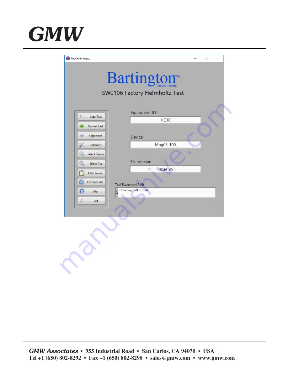
Figure 6: Factory Test Software
The calibration procedure requires measurements to be taken in two opposite directions for each
coil axis. Each axis is tested independently from the others. When applying a field to X, the sensor will be
rotated about its X axis.
Below is described the method used when the X axis of the coil is energised. The same procedure
will apply for Y and Z. As the method is however similar for the other two axes, we will only provide photos
showing the position of the sensor, and the potentiometers which need adjustment for each axis.
o
X axis
For all sensor placements, it is recommended to fit the sensor in the mounting jig several times
and monitor the angular errors given. You should achieve repeatable errors across multiple positioning of
the sensor.
Place the Mag-13 sensor in the supplied mounting jig so that the magnetometer axes match that
of the coil. This will be called position 0.