RDG603A11 - Issue 8 - Shire 14 70, 85 & 130 WB Owners
Manual Page 21 of 50
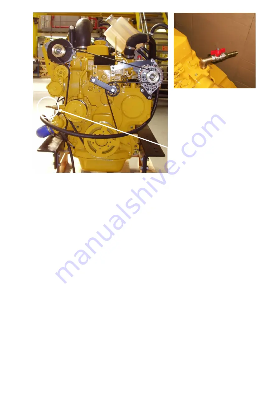
Figure 3-8: Shire 85 WB Calorifier Connections
14.
Control Cables
•
Connect throttle and gear shift cables.
•
With the engine off, ensure that the engine speed control cable achieves full travel
from idle to full speed.
•
Check the gearshift selects positively and that the drive direction corresponds with
the gearshift lever. Ensure that the gearbox control lever and the gearshift lever are
both in neutral before connection.
•
Set gearshift control to neutral position, and the speed control to idle.
15.
Domestic
Battery
Bank (with optional Twin Alternator Engines)
Domestic battery banks that are too large create excessive loads on the domestic
alternator. Alternators running at maximum output for prolonged periods of time will
eventually fail; alternators that fail due to the battery bank being over the maximum
recommended size will not be covered by warranty.
Higher output alternators or travelpower kits are available; if larger battery banks are
required discuss your individual power requirements with the boat builder.
•
The maximum domestic battery bank is calculated using the following:
Calorifier
inlet
Optional:
Calorifier Outlet (located on
rear of engine)


